Liftable and lowerable cable support device

A cable support and cable technology, applied in the direction of electrical components, etc., can solve the problems of increasing the construction period, increasing the cost of cable laying, increasing the consumption of manpower, etc.

Inactive Publication Date: 2018-06-22
巴音慕琅高新技术股份有限公司
View PDF0 Cites 2 Cited by
  • Summary
  • Abstract
  • Description
  • Claims
  • Application Information

AI Technical Summary

Problems solved by technology

[0003] Most of the existing cable supports adopt a fixed structure, and the position is fixed after the installation is completed. With the continuous advancement of the construction process, it is often necessary to move the position of the cable support. At this time, it is necessary to disassemble the cable support and then install it. Doing not only increases the consumption of manpower, increases the cost of cable laying, but also increases the construction period

Method used


Image

  • Liftable and lowerable cable support device
  • Liftable and lowerable cable support device

Examples


Embodiment Construction

[0018] The present invention will be further described below in conjunction with the drawings, but the protection scope of the present invention is not limited to the following.

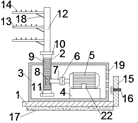
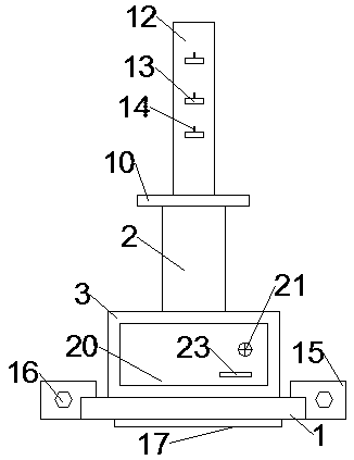
[0019] Such as Figure 1~2 As shown, a liftable cable support device includes a base 1, a lifting column 2 and a cable support assembly. A box 3 is fixedly installed above the base 1, and a motor mounting seat 4 is fixedly installed inside the box 3 A motor 5 is fixedly mounted on the upper end surface of the motor mounting base 4, the motor 5 is connected to the rotating shaft 7 through a coupling 6, the end of the rotating shaft 7 is connected to a gear 8, and one side of the lifting column 2 is fixedly mounted with a tooth Article 9, the two ends of the lifting column 2 are respectively provided with an upper limit plate 10 and a lower limit plate 11, one end of the lifting column 2 is located inside the box 3, and the other end of the lifting column 2 extends through the box 3 to the box Outside th...


PUM


Abstract

The invention discloses a liftable and lowerable cable support device, which comprises a base, a lifting and lowering column and a cable support assembly, wherein a box body is arranged on the base; the box body is internally provided with a motor mounting seat; a motor is fixedly arranged on the upper end surface of the motor mounting seat; the motor is connected with a rotation shaft through a coupler; the rotation shaft is connected with a gear; the lifting and lowering column is provided with a rack; two ends of the lifting and lowering column are provided with an upper limiting plate anda lower limiting plate; one end of the lifting and lowering column is located inside the box body; the other end of the lifting and lowering column passes through the box body and extends outside thebox body; the gear is engaged with the rack; the cable support assembly comprises a vertical column and a cable support arm; the vertical column is provided with the cable support arm; the cable support arm is provided with a cable baffle; the vertical column is fixedly connected with the upper limiting plate; and the motor is electrically connected with an outer controller. According to the liftable and lowerable cable support device, through match effects among the motor, the gear and the rack, the purpose of adjusting the height of the cable support is realized; and through arranging a moisture-proof plate at the lower part of the base, a moisture-proof role is effectively played.

Description

Technical field [0001] The invention relates to the technical field of cable support, in particular to a liftable cable support device. Background technique [0002] In the current field of power technology, there is a power auxiliary device used to support cables when laying cables, called cable brackets. Cable brackets are generally laid in cable trenches and tunnels. Commonly used cable brackets include angle steel brackets and Fabricated bracket. [0003] Most of the existing cable brackets use a fixed structure, and the position is fixed after the installation is completed. With the continuous progress of the construction process, it is often necessary to move the position of the cable bracket. At this time, the cable bracket needs to be disassembled and then installed. This not only increases the manpower consumption and the cost of cable laying, but also increases the construction period. Summary of the invention [0004] The purpose of the present invention is to overcome ...

Claims


Application Information

Patent Timeline
Patent Type & Authority Applications(China)
IPC IPC(8): H02G3/04
CPCH02G3/04
Inventor 胥静王中磊张俊华陈燕萍徐万均夏哲郝宏伟王海吴宏宇
Owner 巴音慕琅高新技术股份有限公司
Why Eureka
Try Eureka