Ultra low loss optical fiber replacement scheduling method and system in backbone network

A scheduling method and backbone network technology, applied in the direction of transmission system, digital transmission system, multiplexing system selection device, etc., can solve the problems affecting the optimization effect of network operators, etc.

Active Publication Date: 2018-06-22
SUZHOU UNIV
View PDF3 Cites 11 Cited by
  • Summary
  • Abstract
  • Description
  • Claims
  • Application Information

AI Technical Summary

Problems solved by technology

But at the same time, different ultra-low loss optical fiber replacement sequences will seriously affect the optimization effect of network operators

Method used


Image

  • Ultra low loss optical fiber replacement scheduling method and system in backbone network
  • Ultra low loss optical fiber replacement scheduling method and system in backbone network
  • Ultra low loss optical fiber replacement scheduling method and system in backbone network

Examples


Embodiment 1

[0101] In this embodiment, the ultra-low-loss optical fiber replacement scheduling method in the backbone network is called the MG strategy, which specifically includes:

[0102] S1 respectively calculates the gain of each optical fiber link after replacement, that is, calculates the number of frequency slots FS reduced after the replacement of each optical fiber link and multiplies the remaining time until all the remaining optical fiber links are replaced;

[0103] S2 selects one of the optical fiber links with the highest gain after replacement of the optical fiber link for replacement;

[0104] S1 to S2 are repeated until all fiber links that need to be replaced are replaced.

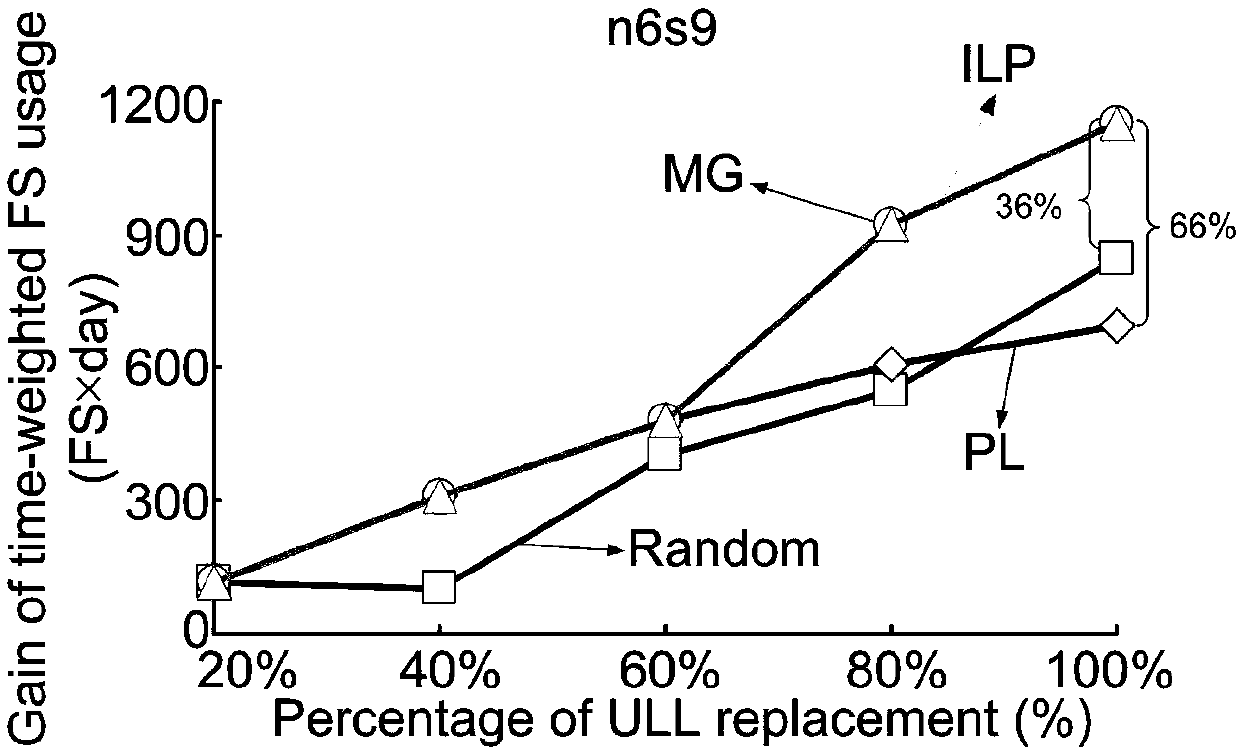
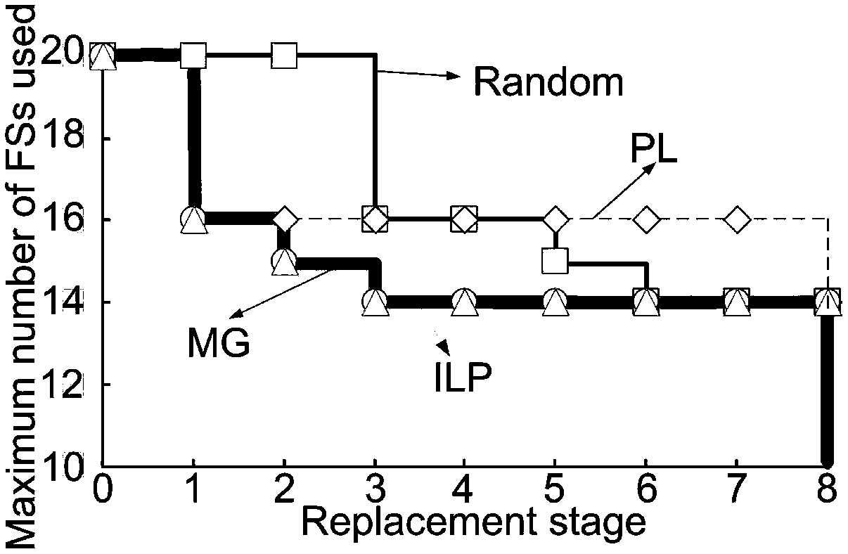
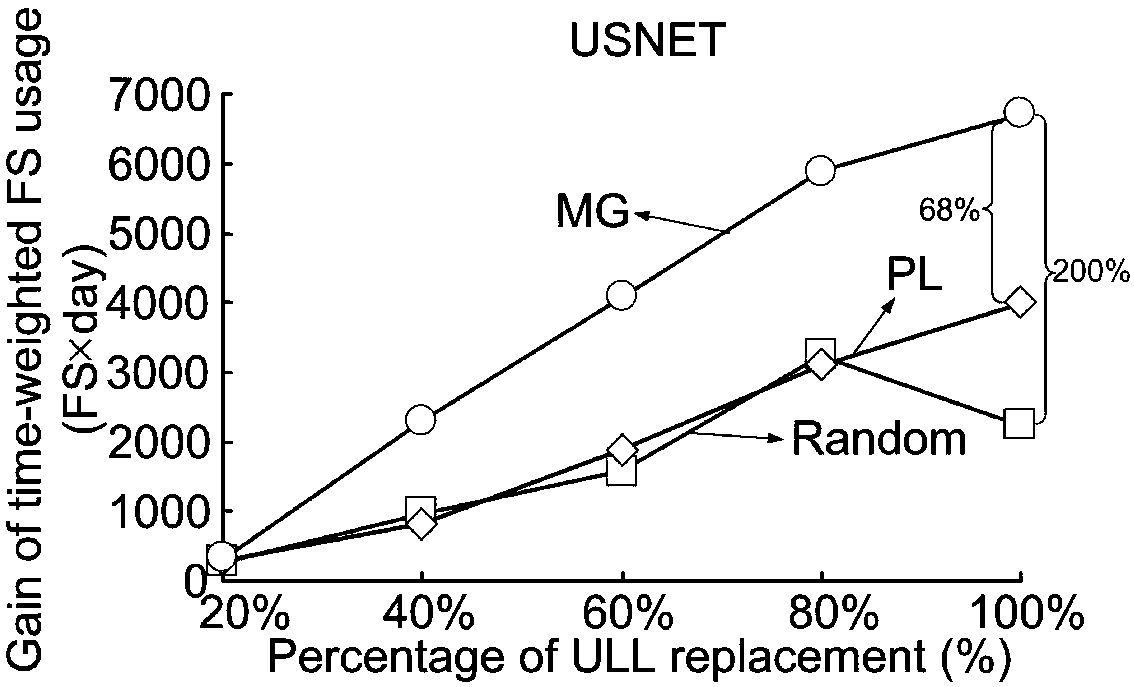
[0105] In this embodiment, two test networks are taken as examples, namely the n6s9 network with 6 nodes and 9 links and the USNET with 24 nodes and 43 links. In each fiber link, there are at most 320 FSs, each FS has a bandwidth of 12.5-GHz spectrum. In each optical fiber link, optical amplifiers...

Embodiment 2

[0110] The ultra-low-loss optical fiber replacement scheduling method in the backbone network of this embodiment is applicable to small-scale networks with a small amount of computation, and the specific methods include:

[0111] Construct the linear programming model ILP, take the topology of the optical fiber link with replacement as input, and run the linear programming model ILP with the goal of maximizing the gain of the optical fiber link replacement process, where the gain formula of the replacement process is: ∑ k∈1..P C k-1 ·T k ; The constraints of the linear programming model ILP are:

[0112] Constraint 1 ensures that the maximum number of frequency slots FS used in the entire network is greater than the last frequency slot FS occupied by any optical channel, the expression:

[0113] Constraint 2 is guaranteed to meet the optical channel service request between each node pair after each fiber link is replaced, the expression:

[0114]Constraints 3 and 4 ensu...

Embodiment 3

[0154] The ultra-low loss optical fiber replacement dispatching system in the backbone network of this embodiment includes:

[0155] The gain calculation unit is used to calculate the gains after the replacement of each fiber link before selecting the current replacement link, that is, calculate the number of frequency slots FS reduced after the replacement of each fiber link and multiply it until the rest of the fiber links are completed. replace the remaining time;

[0156] The replacement link selection unit is used to select one of the optical fiber links with the highest gain after the replacement of the optical fiber link to complete the current optical fiber link replacement according to the result of the gain calculation unit;

[0157] The gain calculation unit and the replacement link selection unit operate repeatedly until all the optical fiber links that need to be replaced are completely replaced.

[0158] In this embodiment, a linear programming model ILP is also...


PUM


Abstract

The invention relates to an ultra low loss optical fiber replacement scheduling method and system in a backbone network for improving the spectrum utilization efficiency of an operator. The method provided by the invention comprises the following steps: S1 calculating gains after the replacement of optical fiber links, that is, calculating remaining times of reduced frequency slot FS after the replacement of the optical fiber links to complete replacement of the rest optical fiber links; S2, selecting the optical fiber link with the highest gain after the replacement of one optical fiber linkfor replacement; and repeating S1 to S2 until all optical fiber links needing to be replaced are completely replaced. According to the ultra low loss optical fiber replacement scheduling method and system, by determining the most reasonable optical fiber replacement sequence, the spectrum resources are saved for the operators as much as possible for additional service use.

Description

technical field [0001] The invention relates to a method and system for replacing and scheduling ultra-low loss optical fibers in a backbone network. Background technique [0002] In order to meet the growing demand for communication services, ultra-long-distance optical transmission systems are expected to use ultra-low-loss optical fibers to improve transmission capacity and spectral efficiency. Ultra-low loss (ULL) optical fiber SMF-28 produced by Corning has been commercially available. Thanks to the development of ultra-low-loss optical fiber technology, it is possible for ultra-low-loss optical fiber to fully replace standard single-mode optical fiber to meet future communication needs. [0003] In the study of the advantages of ultra-low loss optical fiber, there is an important practical problem, that is, network operators have limited human resources for replacing optical fibers, and it often takes several weeks to replace existing optical fibers with ultra-low los...

Claims


Application Information

Patent Timeline
Patent Type & Authority Applications(China)
IPC IPC(8): H04L12/24H04Q11/00
CPCH04L41/145H04Q11/0062H04Q2011/0079
Inventor 沈纲祥李泳成蔡安亮
Owner SUZHOU UNIV
Why Eureka
Try Eureka