
Dynamic anti-interference receiver device and method

A receiver and dynamic technology, applied in electrical components, transmission systems, etc., can solve the problems of interference, ordinary filters are difficult to achieve high system isolation, and cannot achieve system anti-interference ability, etc., to save spectrum resources and enhance anti-interference. The effect of blocking performance

Inactive Publication Date: 2016-05-18
BEIJING XINWEI TELECOM TECH
View PDF5 Cites 6 Cited by
  • Summary
  • Abstract
  • Description
  • Claims
  • Application Information

AI Technical Summary

Problems solved by technology

However, these wireless communication systems in very adjacent frequency bands are bound to encounter interference problems caused by coexistence and co-location between systems. If ordinary filters (usually cavity filters) are used for anti-interference, ordinary filters are difficult If the requirements of high isolation between systems are met, the purpose of improving the system's anti-interference ability cannot be achieved

Method used


Image

  • Dynamic anti-interference receiver device and method
  • Dynamic anti-interference receiver device and method

Examples


Embodiment 1

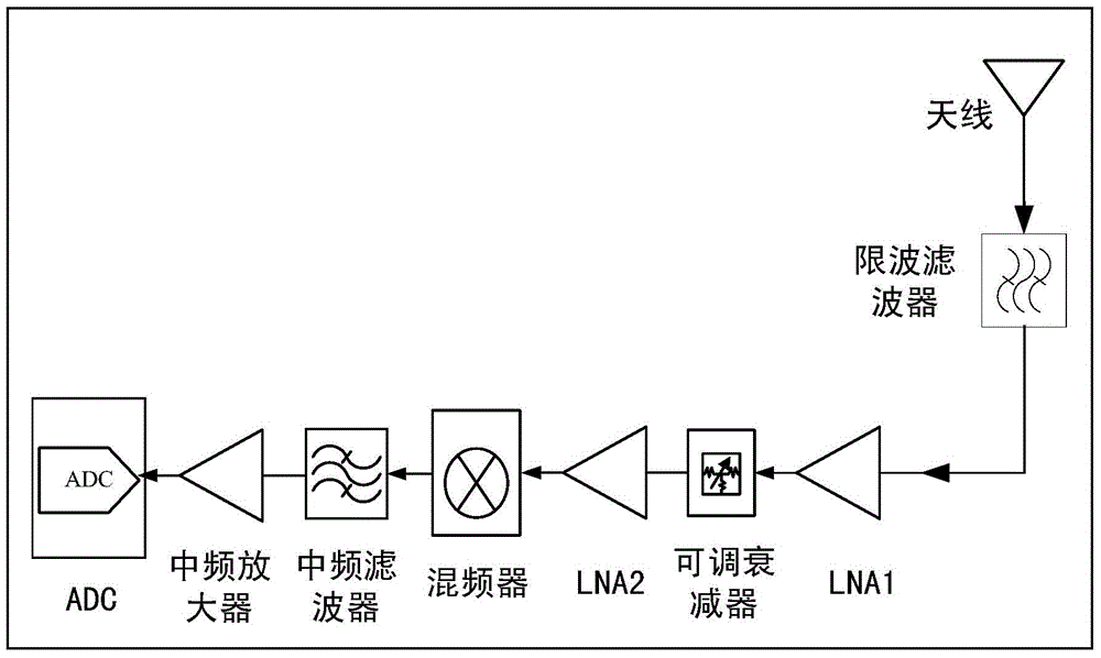
[0018] This embodiment takes the design of the uplink receiver of the McWiLL system in the 1785MHz-1802.5Mhz frequency band as an example to illustrate how to realize the coexistence of the McWiLL system in the 1785MHz-1802.5Mhz frequency band and the DCS1800M system. The McWiLL system is a TDD system, and its uplink frequency range is 1785-1802.5MHz, while the frequency range of 1805MHz-1850MHz is the downlink frequency range of the DCS1800M system. When the two coexist, the uplink of the McWiLL system is easily affected by the downlink of the DCS1800M system.

[0019] The key points of the McWiLL uplink receiver design of this embodiment are: (1) in order to strengthen the interference to very adjacent frequency bands, a wave limiting filter is introduced in the receiver design; (2) reduce the stage of the front-end amplifier of the mixer number, only two-stage LNA low-noise amplifiers are reserved, and the mixer is filtered first and then amplified. Using such a link allocat...

Embodiment 2

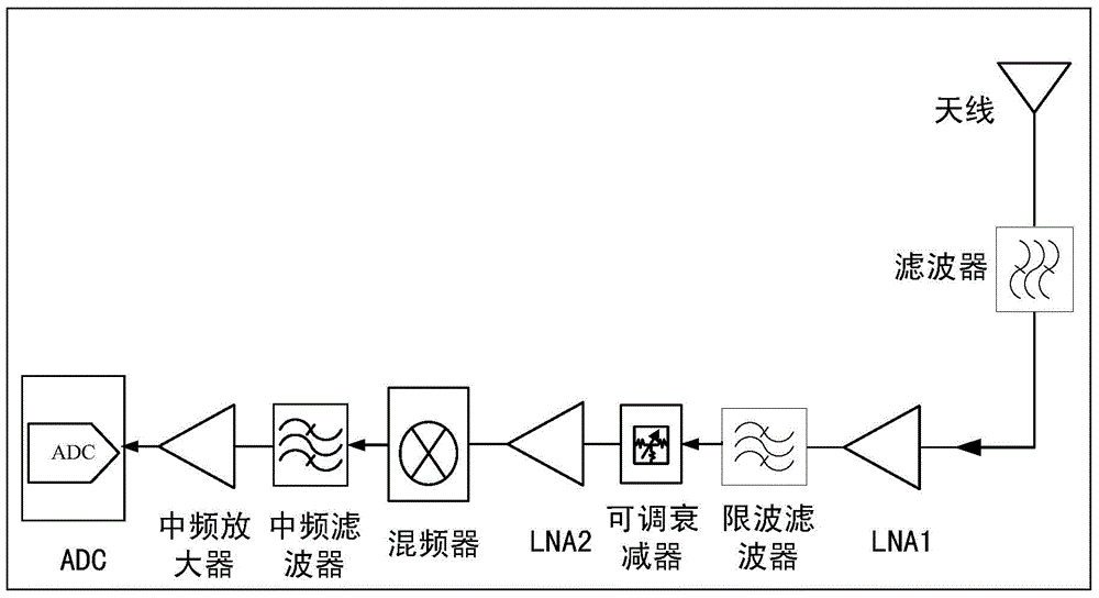
[0024] The insertion loss of the wave-limiting filter is generally relatively large, and the use of the wave-limiting filter will reduce the sensitivity of the uplink receiver while reducing the noise figure of the uplink. In order to further enhance the anti-blocking capability and not reduce the sensitivity of the uplink receiver, this embodiment improves the McWiLL uplink receiver on the basis of Embodiment 1. Its structural block diagram is as follows figure 2 shown. In the improved receiver, the wave-limiting filter is placed between two stages of LNAs, and the antenna front-end filter does not use the wave-limiting form but a common filter, and the configuration of other parts is the same as that of the first embodiment. The improved anti-jamming ability of the receiver is better than that of the receiver in Embodiment 1. The advantage is that the antenna front-end filter mainly plays the role of suppressing emission spurs and lightning protection, so that the insertion...


PUM


Abstract

The invention provides a dynamic anti-interference receiver device comprising a wave-limiting filter, a first-stage low-noise amplifier, a second-stage low-noise amplifier, an adjustable attenuator, a mixer, an intermediate-frequency filter, an intermediate-frequency amplifier, an analog-to-digital converter. The wave-limiting filter is arranged in front of the first-stage low-noise amplifier and is used for inhibiting signals from other communication systems; the adjustable attenuator arranged between the first-stage low-noise amplifier and the second-stage low-noise amplifier is used for reducing the front-end gain of the receiver device; and the intermediate-frequency filter arranged between the mixer and the intermediate-frequency amplifier is used for inhibiting the interference. With the device, a co-station and a co-address effect of wireless systems of adjacent frequency bands can be realized; and the frequency resources can be fully utilized and saved.

Description

technical field [0001] The invention relates to the field of wireless communication, in particular to a dynamic anti-jamming receiver device and method. Background technique [0002] In traditional communication system frequency resource division, many guard frequency bands are reserved to support different communication systems, which invisibly causes a great waste of limited spectrum resources. With the technological development of communication technology and components, in order to make full use of frequency resources, new wireless systems can be developed using guard frequency bands. However, these wireless communication systems in very adjacent frequency bands are bound to encounter interference problems caused by coexistence and co-location between systems. If ordinary filters (usually cavity filters) are used for anti-interference, ordinary filters are difficult If the requirement of high isolation between systems is met, the purpose of improving the anti-interferen...

Claims


Application Information

Patent Timeline
IPC IPC(8): H04B1/10
Inventor 蔡克辉
Owner BEIJING XINWEI TELECOM TECH
Learn More