Differential modulation and demodulation method applied to spatial modulation system

A technology of differential modulation and spatial modulation, which is applied in the direction of preventing/detecting errors through diversity reception, and can solve problems such as occupying transmission system spectrum resources, channel response changes, and spectrum efficiency decline

Inactive Publication Date: 2014-01-22
PEKING UNIV
View PDF0 Cites 6 Cited by
  • Summary
  • Abstract
  • Description
  • Claims
  • Application Information

AI Technical Summary

Problems solved by technology

However, in some cases it may be difficult for us to obtain a sufficiently accurate estimate of the channel response
For example, in high-speed mobile scenarios, the channel response changes too quickly, and the accuracy of channel est

Method used


Image

  • Differential modulation and demodulation method applied to spatial modulation system
  • Differential modulation and demodulation method applied to spatial modulation system
  • Differential modulation and demodulation method applied to spatial modulation system

Examples


Embodiment Construction

[0044] In order to make the above objects, features and advantages of the present invention more comprehensible, the present invention will be further described in detail below in conjunction with the accompanying drawings and specific embodiments.

[0045] To describe the emission modulation space more clearly The following table takes the BPSK symbol modulation of two transmitting antennas as an example, and lists a transmission modulation space and a block-to-space The mapping method, see the following table for details:

[0046]

[0047]

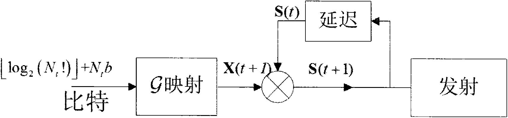
[0048] figure 1 The differential modulation process in the present invention is shown, and its modulation process is described as follows:

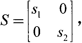
[0049] Initial time slots 1 and 2 transmit signal S(1), S(1) can be any one belonging to the transmission modulation space of the present invention signal, may wish to take S ( 1 ) = ...


PUM


Abstract

The invention provides a differential modulation and demodulation method applied to a spatial modulation system. According to the differential modulation and demodulation method provided by the invention, extension is performed on an emission modulation space of the traditional spatial modulation technology. By adopting the differential modulation and demodulation method provided by the invention, sending end modulation and receiving end demodulation can be performed without knowing channel state information, and therefore, channel estimation can be avoided, and the complexity of a receiver is reduced. Meanwhile, pilot frequency interpolation is avoided, so that a spectrum resource can be saved. Moreover, the differential modulation and demodulation method applied to the spatial modulation system is suitable for a high-speed mobile scene of which the channel response change is fast.

Description

technical field [0001] The invention relates to the technical field of mobile communication, in particular to a method for differential modulation and demodulation of space modulation signals. Background technique [0002] Spatial Modulation (SM, Spatial Modulation) is a novel Multiple-Input Multiple-Output (MIMO, Multiple-Input Multiple-Output) technology. SM modulation has two information carrying units, one is the traditional transmission symbol, and the other is the antenna serial number. In SM modulation, each time slot selects a symbol from the traditional constellation diagram, and selects a transmit antenna to activate to transmit this symbol. Both the symbol and the antenna number (or spatial position) of the activated antenna carry transmission information. Therefore, compared with the traditional MIMO technology, V-BLAST, etc., SM modulation can completely avoid signal synchronization and interference problems between transmitting antennas and greatly reduce the...

Claims


Application Information

Patent Timeline
IPC IPC(8): H04L1/06
Inventor 程翔卞宇阳温淼文焦秉立
Owner PEKING UNIV
Why Eureka
Try Eureka