Stamping die wire connector

A technology for stamping dies and connectors, which is applied in the direction of connection, conductive connection, clamping/spring connection, etc. It can solve the problems of affecting wiring efficiency, affecting the service life of stamping dies, and material waste, so as to avoid position deviation and ensure firmness The effect of clamping and easy operation

Pending Publication Date: 2018-06-26
CHONGQING YINSHENG MOLD
View PDF0 Cites 0 Cited by
  • Summary
  • Abstract
  • Description
  • Claims
  • Application Information

AI Technical Summary

Problems solved by technology

At present, the commonly used connection method is to use insulating tape to bind, but this method is more suitable for cables with small diameters. If it is applied to a stamping die with high power, there will be a problem of unreliable fixation. In this way, not only It will affect the production quality, and at the same time, it will seriously affect the service life of the stamping die
In addition, the existing connection methods not only affect the efficiency of wiring, but also are not recyclable, which will cause waste of materials

Method used


Image

  • Stamping die wire connector
  • Stamping die wire connector
  • Stamping die wire connector

Examples


Embodiment 1

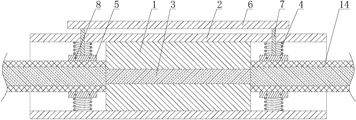
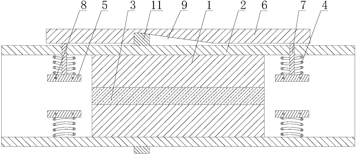
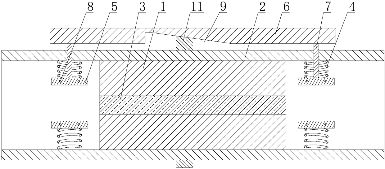
[0031] Such as Figure 1 to Figure 5 As shown, a stamping die connector includes an inner insulating cylinder 1 and an outer insulating cylinder 2 sleeved outside the inner insulating cylinder 1 and arranged coaxially with the inner insulating cylinder 1. The axial length of the outer insulating cylinder 2 is longer than that of the inner insulating cylinder. The axial length of the cylinder 1, and both ends of the inner insulation cylinder 1 are located in the outer insulation cylinder 2, and the inner insulation cylinder 1 is provided with a conductor that is coaxially arranged with the inner insulation cylinder 1 and whose two ends pass through the two ends of the inner insulation cylinder 1 3;

[0032] The inner walls of both ends of the outer insulating cylinder 2 are provided with a plurality of elastic members 4 arranged radially, the free ends of the elastic members 4 are fixedly connected with splints 5, and also include a lifting rod 6 arranged outside the outer insu...


PUM


Abstract

The invention discloses a stamping die wire connector. The stamping die wire connector comprises an inner insulating cylinder and an outer insulating cylinder; an electric conduction body is arrangedin the inner insulating cylinder; the inner walls of two ends of the outer insulating cylinder are provided with a plurality of elastic components; the free ends of the elastic components are connected with clamping plates; the stamping die wire connector further comprises a lifting rod arranged outside the outer insulating cylinder; two ends of the lifting rod are provided with connecting columns; and the connecting columns at the two ends of the lifting rod are respectively connected with two clamping plates in the plurality of clamping plates at the two ends of the outer insulating cylinder. According to the stamping die wire connector of the invention, the lifting rod is adopted, so that the areas of clamping regions at the two ends of the outer insulating cylinder can be changed synchronously, and therefore, cables can be installed at and disassembled from the two ends of the outer insulating cylinder synchronously, and the connection or disconnection of two cables can be realized. The stamping die wire connector has the advantages of firm clamping, simple operation and low cost.

Description

technical field [0001] The invention relates to a stamping die connector. Background technique [0002] Due to the optimization of the layout in the workshop, when the position of the stamping die needs to be adjusted, the cable of the stamping die needs to be lengthened. At present, the commonly used connection method is to use insulating tape to bind, but this method is more suitable for cables with smaller diameters. If it is applied to a stamping die with high power, there will be a problem of unreliable fixation. In this way, not only It will affect the production quality, and at the same time, it will seriously affect the service life of the stamping die. In addition, the existing connection method not only affects the efficiency of wiring, but also is not recyclable, which will cause waste of materials. Contents of the invention [0003] The purpose of the present invention is to overcome the deficiencies of the prior art, to provide a stamping die connector, thro...

Claims


Application Information

Patent Timeline
IPC IPC(8): H01R4/48
CPCH01R4/4863
Inventor 邱建华
Owner CHONGQING YINSHENG MOLD
Why Eureka
Try Eureka