Collodion slab mop cleaning barrel

A technology of flat mop and cleaning bucket, which is applied to cleaning carpets, floors, cleaning equipment, etc. It can solve the problems of large size, inability to clean in small spaces, inconvenient use, etc., and achieves convenient operation, stable and reliable water squeezing effect, and movement stable effect

Pending Publication Date: 2018-06-29
邱新保
View PDF6 Cites 2 Cited by
  • Summary
  • Abstract
  • Description
  • Claims
  • Application Information

AI Technical Summary

Problems solved by technology

[0003] The existing collodion mop has the problems of large volume, inconvenient use, especially the inability to clean a narrow space
The collodion flat mop can effectively overcome the above-mentioned technical problems, but there is no mechanism suitable for squeezing the working head of the collodion flat mop at present

Method used


Image

  • Collodion slab mop cleaning barrel
  • Collodion slab mop cleaning barrel
  • Collodion slab mop cleaning barrel

Examples


Embodiment 1

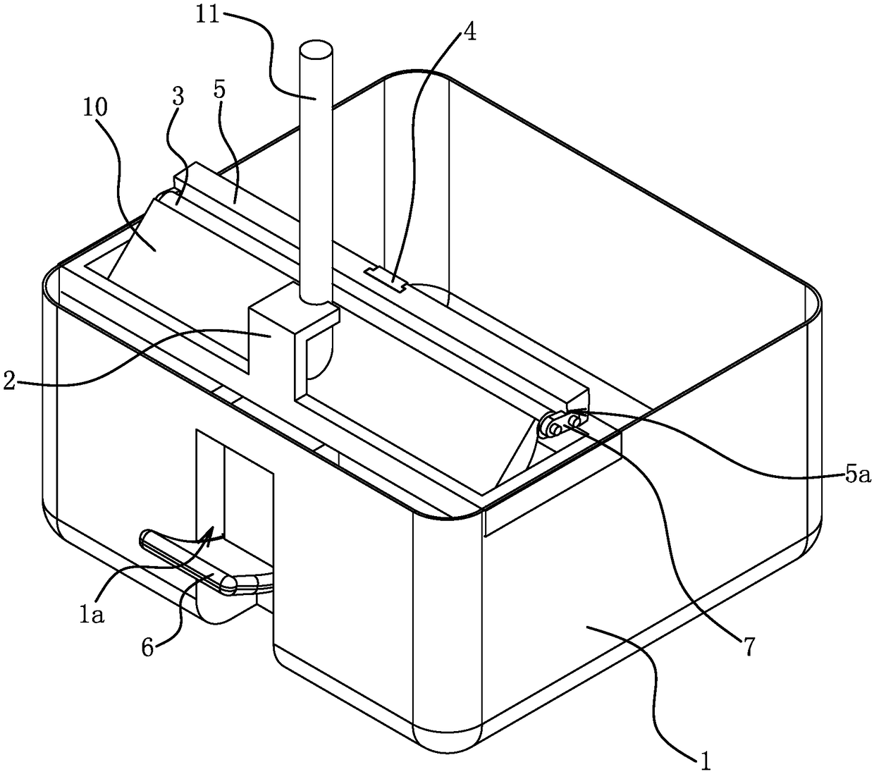
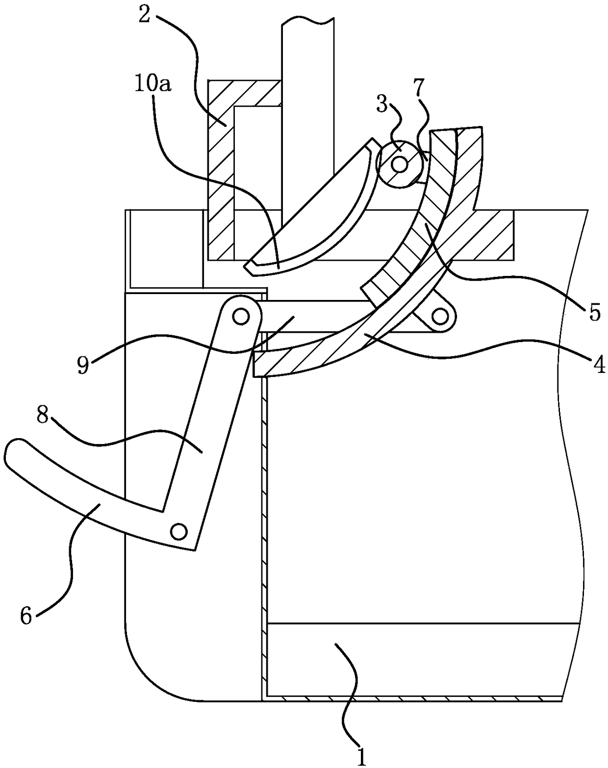
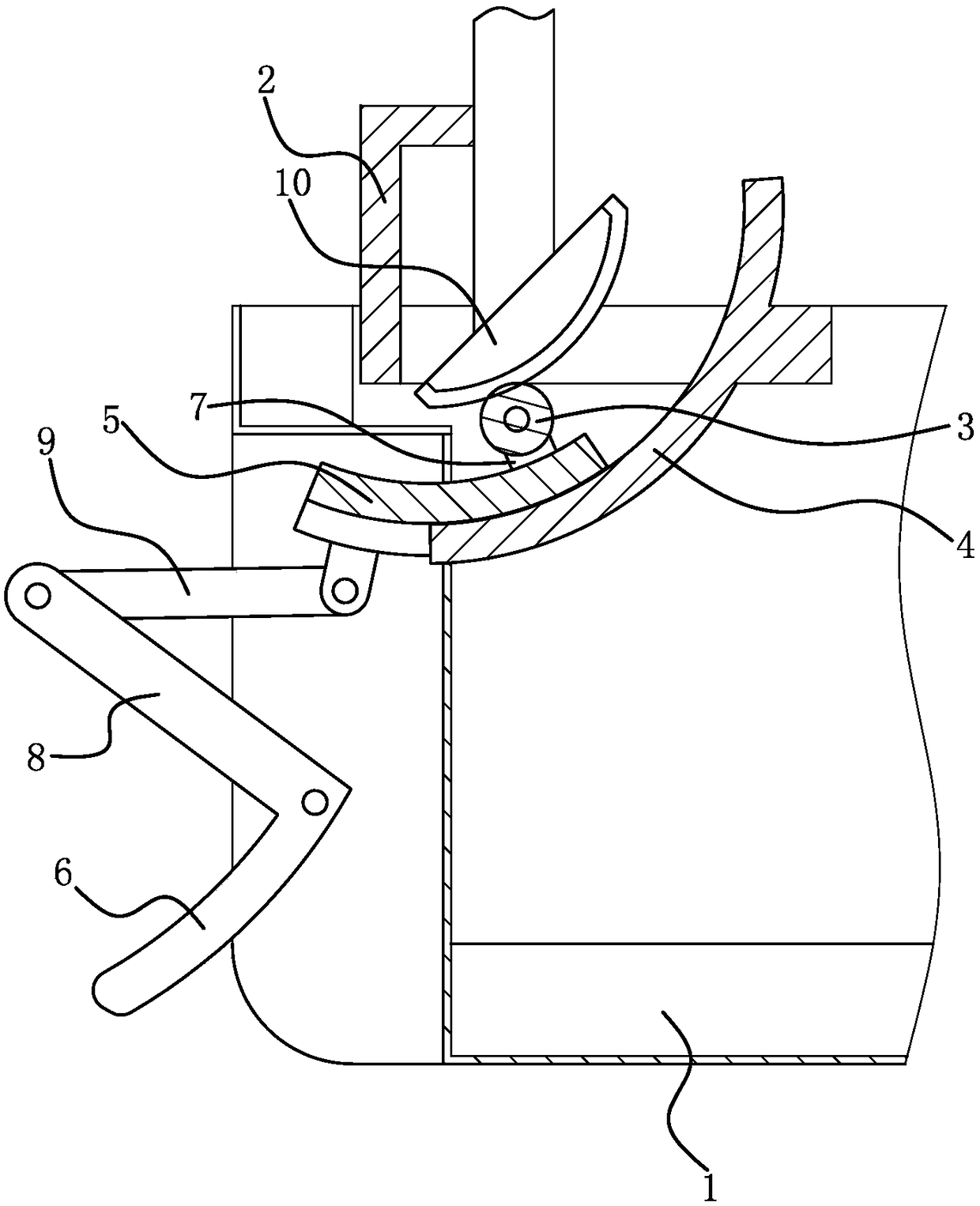
[0018] Such as Figure 1 to Figure 3 As shown, the collodion mop cleaning bucket includes a bucket body 1, a backing 2, a squeezing roller 3, an arc guide rail 4, a sliding seat 5 and a pedal 6.

[0019] The brim of barrel body 1 is fixedly connected with backing 2, and backing 2 is for the working head 10 backside of collodion flat mop or mop handle 11 root parts to lean against, realizes limiting that collodion flat mop moves upwards. By controlling the inclination angle of the abutment surface in the backer 2, the orientation of the working face of the working head 10 can also be controlled; The collodion flat mop leaning against the backer 2 is in the best water-squeezing state.

[0020] The arc guide rail 4 is located in the barrel body 1 and both ends of the arc guide rail 4 are fixedly connected with the barrel body 1, and the concave surface of the arc guide rail 4 faces the backer 2. The position and orientation of the arc guide rail 4 match the working surface of t...

Embodiment 2

[0028] The structure and principle of this embodiment are basically the same as those of Embodiment 1, and the basic similarities will not be described redundantly, only the differences will be described, and the differences lie in the transmission mechanism. The transmission mechanism includes a steel cable and a reversing roller connected in rotation with the barrel body 1. The steel cable passes through the wheel surface of the reversing roller. One end of the steel cable is connected with the sliding seat 5, and the other end of the steel cable is connected with the pedal 6. A return spring is provided between the seat 5 and the barrel body 1, and a second spring may not be arranged between the pedal 6 and the barrel body 1 . When people step on the pedal 6, the pedal 6 swings and pulls the cable, and the cable pulls the slide 5 to move down along the arc guide rail 4; when the pedal 6 is released, the slide 5 is forced to reset under the elastic force of the return spring,...


PUM


Abstract

The invention provides a collodion slab mop cleaning barrel and belongs to the technical field of living articles. The collodion slab mop cleaning barrel solves the problem that there are no suitabledewatering mechanisms for collodion slab mop working heads at present. The collodion slab cleaning barrel includes a barrel body, a backing part for restraining a collodion slab mop from moving upwards is fixed to the barrel body, and an inner cavity of the barrel body is internally provided with a dewatering roller, an arc guide rail and a sliding base; the arc guide rail is fixedly connected with the barrel body, the sliding base is arranged on the arc slide rail, and the dewatering roller is positioned on the inner side of the arc guide rail and rotatably connected with the sliding base; apedal is also swingingly connected to the barrel body and connected with the sliding base through a transmission mechanism, wherein the transmission mechanism can drive the sliding base to move alongthe arc guide rail when the pedal swings. The collodion slab mop cleaning barrel can achieve dewatering of collodion of the collodion slab mop. The collodion slab mop cleaning barrel can be used for not only cleaning a working head but also dewatering the working head, so that the collodion slab mop cleaning barrel has the advantages that the functions are complete and the structure is compact.

Description

technical field [0001] The invention belongs to the technical field of daily necessities, and relates to a collodion mop, in particular to a collodion flat mop cleaning bucket. Background technique [0002] The working head of the collodion mop is made of polyvinyl alcohol collodion. At present, the water squeezing method of the working head of the collodion mop is mainly to use the roller shafts located on both sides of the working head to squeeze the working head and to squeeze the working head by turning over the plate. [0003] The existing collodion mop has the problems of large volume, inconvenient use, and especially the inability to clean a narrow space. The collodion flat mop can effectively overcome the above-mentioned technical problems, but there is no mechanism suitable for squeezing the working head of the collodion flat mop at present. Contents of the invention [0004] The invention proposes a collodion flat mop cleaning bucket, and the technical problem ...

Claims


Application Information

Patent Timeline
IPC IPC(8): A47L13/59
CPCA47L13/59
Inventor 邱新保
Owner 邱新保
Why Eureka
Try Eureka