Skeletal traction reposition fixing device and method for treating limb fractures
A fixation device and bone traction technology, applied in the medical field, can solve the problems of fixation damage, device compression, and inability to adjust the direction of the traction force, and achieve the effects of strong stability, easy portability, and enhanced stability.
- Summary
- Abstract
- Description
- Claims
- Application Information
AI Technical Summary
Problems solved by technology
Method used
Image
Examples
Embodiment 1
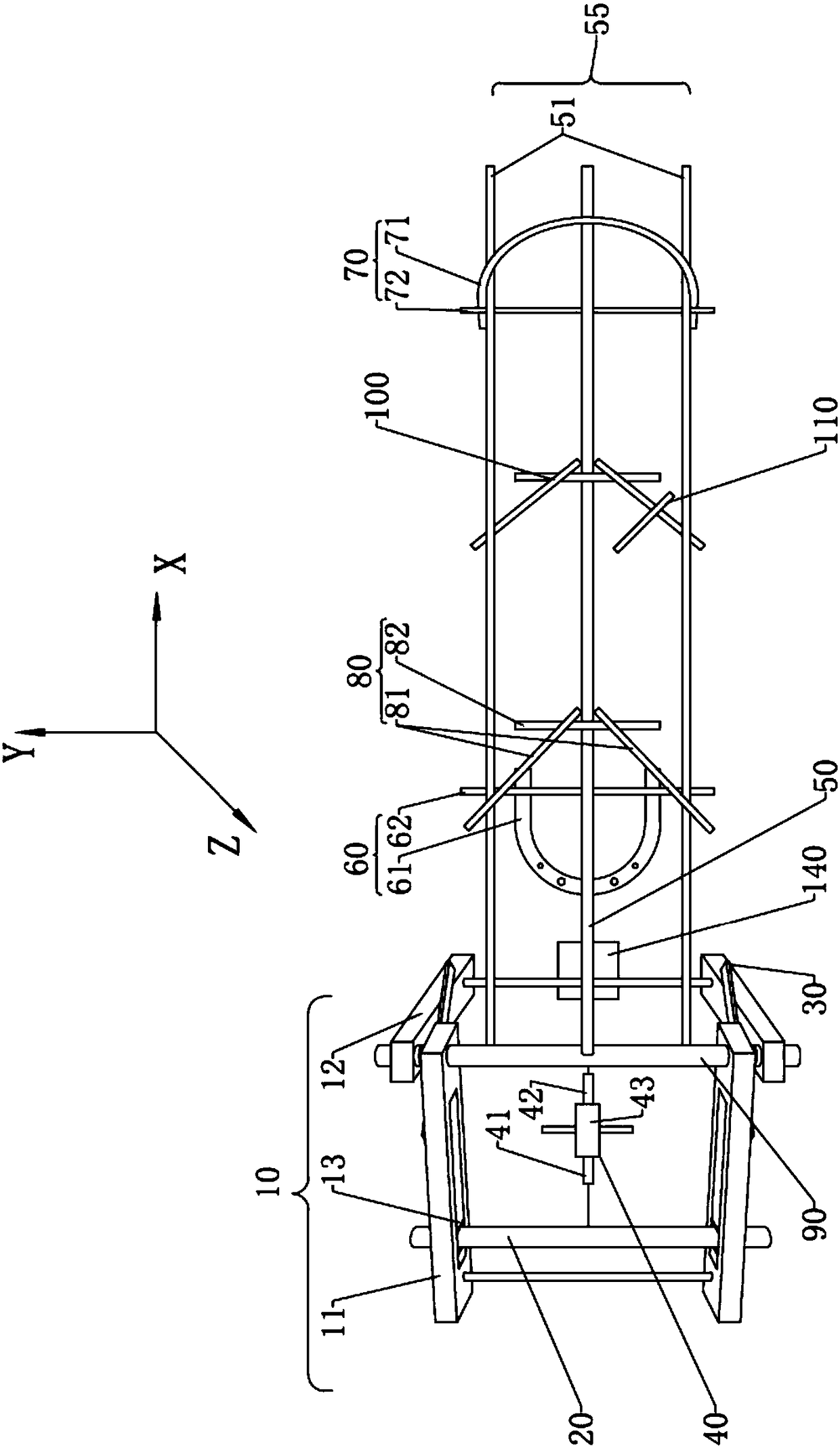
[0043] Such as figure 1 The shown device is the first embodiment provided by the present invention, including a reset bracket 10, a traction bar 20, a locking plate 30, an adjustable screw 30, a screw tightener 40, a support rod 50, a side support rod 51, The traction mechanism 60 , the fixing mechanism 70 and the first adjustable triangular bracket 80 .
[0044] The reset support 10 is a foldable support composed of the first square frame 11 and the second square frame 12. The two groups of square frames share the rotating shaft 90; hole 13, the traction bar 20 is fixed on the reset bracket 10 through a set of positioning holes; The opposite inner sides of the side bars of the group are respectively provided with locking buckles, through which the two groups of locking pieces 30 are respectively connected to the two groups of square frames to fix the reset support 10; The card slot changes the height of the reset bracket 10; the positioning hole 13 at different positions ca...
no. 1 example
[0054] The first embodiment is a ring-shaped three-axis traction reduction and fixation device, which is a three-axis anti-traction, and the affected limb is at the center of the three axes, so that the traction force line is the center of traction, which is conducive to fracture reduction; the fixing mechanism is fixed on the triangular shaft bracket , It will not be displaced with the traction, so there is no compression of the limbs by the traction device.
[0055] The present invention also includes such as Figure 4 The external fixation device 150 shown, the external fixation device 150 includes an external fixation screw 151 and a universal external fixation bracket; The cross-bar needle clamp is provided with screw holes and clamping slides; one end of the two pillars 153 is movably connected to the two ends of the cross-bar 154 respectively, and the other end is screwed into the screw holes of the two cross-bar needle clamps 152 respectively. The two screws are respe...
Embodiment 2
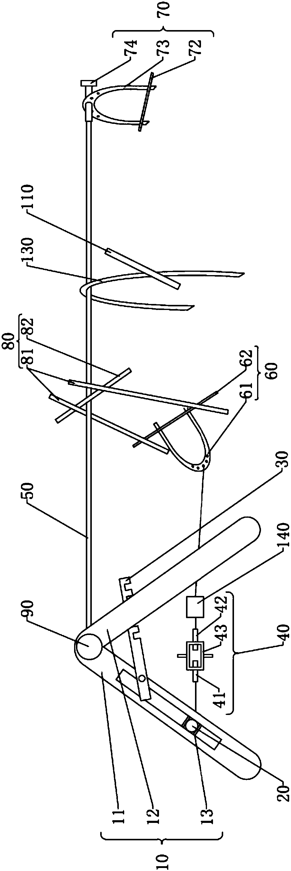
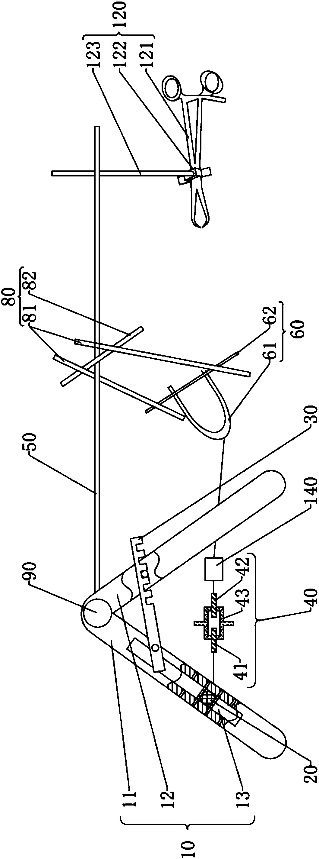
[0066] Such as figure 2 What is shown is the second embodiment provided by the present invention. Since embodiment 2 is a simple configuration of embodiment 1, the description of embodiment 2 is relatively simple. For relevant details, please refer to the description in embodiment 1.
[0067] In the second embodiment, including reset bracket 10, traction cross bar 20, locking plate 30, screw tightener 40, support rod 50, traction mechanism 60, fixing mechanism 70 and first adjustable triangular bracket 80; One end is screwed into the screw hole of the rotating shaft 90 , and the other end is connected to the fixing mechanism 70 .
[0068] The fixing mechanism 70 includes a bow-type fixing device and a second Kirschner wire 72, the bow-type fixing device includes a second traction bow 73 and a connecting sleeve 74; one end of the support rod 50 away from the reset bracket 10 is connected to the connecting sleeve 74, The connecting sleeve 74 is fixedly connected to the top end...
PUM
 Abstract
Description
Claims
Application Information
 - R&D
- Intellectual Property
- Life Sciences
- Materials
- Tech Scout
- Unparalleled Data Quality
- Higher Quality Content
- 60% Fewer Hallucinations
Browse by: Latest US Patents, China's latest patents, Technical Efficacy Thesaurus, Application Domain, Technology Topic, Popular Technical Reports.
© 2025 PatSnap. All rights reserved.Legal|Privacy policy|Modern Slavery Act Transparency Statement|Sitemap|About US| Contact US: help@patsnap.com


