Clamping device for welding of middle grooves

A technology of clamping device and pressing device, applied in welding equipment, auxiliary devices, auxiliary welding equipment and other directions, can solve the problems of low efficiency, long time-consuming clamping and positioning, etc. tight effect

Active Publication Date: 2018-06-29
SHANXI FENXI MINING GRP
View PDF10 Cites 2 Cited by
  • Summary
  • Abstract
  • Description
  • Claims
  • Application Information

AI Technical Summary

Problems solved by technology

[0004] In order to solve the time-consuming and low-efficiency problems of clamping and positioning when the middle groove welding is turned over in the prior art, the present invention proposes a clamping device for middle groove welding

Method used


Image

  • Clamping device for welding of middle grooves
  • Clamping device for welding of middle grooves
  • Clamping device for welding of middle grooves

Examples


Embodiment

[0028] Embodiment: A clamping device for middle slot welding, including an upper pressing device and a lower pressing device oppositely arranged, and a deflection adjustment device is fixedly connected to the opposite sides of the lower pressing plate of the lower pressing device respectively, and the upper pressing device The tightening device and the lower pressing device can be connected with the external platform, or can form a device by itself; combined with the transportation, turning and other tooling during the welding of the middle groove, the external platform can be a transportation platform.

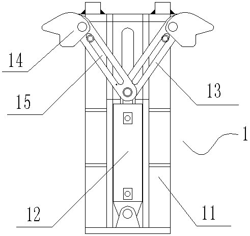
[0029] Such as figure 1 Any deviation adjustment device 1 shown includes a vertical frame 11, a deviation adjustment oil cylinder 12, a set of sliding plates 13 and a set of deviation adjustment blocks 14, and a set of sliding plates 13 includes two strip-shaped sliding plates, each of which is long The strip-shaped sliding plate 13 is provided with a strip-shaped sliding gro...


PUM


Abstract

The invention relates to a clamping device for welding of middle grooves. The clamping device comprises an upper pressing device and a lower pressing device which are arranged oppositely. The two opposite sides of a lower pressing plate of the lower pressing device are fixedly connected with deviation adjusting devices correspondingly. Each deviation adjusting device comprises a vertical frame, adeviation adjusting oil cylinder and a set of sliding plates. Each set of sliding plates comprises two long-strip-shaped sliding plates. Each sliding plate is provided with a long-strip-shaped slidinggroove. The two sliding plates form a V shape. The vertical frames are fixedly connected to one side of the lower pressing plate. The deviation adjusting oil cylinders are arranged on the inner sidesof the vertical frames. The overlapping end of each set of sliding plates is connected with a piston rod of the corresponding deviation adjusting oil cylinder through a pin shaft. The two sliding grooves are symmetrically clamped on the position, on the two sides of the piston rods, of the pin shafts of the vertical frames. The lower pressing device and the upper pressing device clamp middle plates of the middle grooves, the two deviation adjusting oil cylinders simultaneously drive the two sets of sliding plates to correspondingly extend outwards to tightly support the inner sides of the groove edges on the two sides of the middle plates, and clamping and positioning of the middle grooves are completed. The clamping device is simple in structure, and the efficiency is improved.

Description

technical field [0001] The invention relates to the field of middle groove welding equipment, in particular to a clamping device that avoids potential safety hazards when the middle groove of a scraper conveyor is automatically turned over during double-sided welding. Background technique [0002] The middle trough is an integral part of the conveying trough of the scraper conveyor, and is the main part of the scraper conveyor. The middle trough is mainly composed of the middle plate and the side of the baffle plate and the side of the shovel plate on both sides of the middle plate. The middle plate is used for both It is used for carrying materials and is in direct contact with the scraper chain, so the middle plate and the side of the baffle plate and the side of the scraper plate are welded on both sides. The traditional middle groove is turned over after one side is welded, and then the other side is welded by driving overturning or other overturning equipment. The posit...

Claims


Application Information

Patent Timeline
Patent Type & Authority Applications(China)
IPC IPC(8): B23K37/04
CPCB23K37/0443
Inventor 高炳李娜郭振寅黄新李王锋张晓天刘艳勤冯迎春
Owner SHANXI FENXI MINING GRP
Why Eureka
Try Eureka