Uniform plastic rod cutting equipment

A technology for cutting equipment and plastic rods, which is applied in metal processing and other directions, and can solve the problems of being easily cut by cutters, time-consuming and labor-intensive, etc.

Active Publication Date: 2018-06-29
泗县东方塑料有限责任公司
View PDF5 Cites 9 Cited by
  • Summary
  • Abstract
  • Description
  • Claims
  • Application Information

AI Technical Summary

Problems solved by technology

[0005] In order to overcome the shortcomings of time-consuming and labor-intensive cutting of plastic rods by the present invention, easy to be cut by the cutter during the cutting process, and the length of the cut plastic rods is uniform, the technical problem to be solved by the present invention is to provide a time-saving and labor-saving, no-need People can cut without being cut, the cut plastic rods have the same length and the plastic rods are cut evenly

Method used


Image

  • Uniform plastic rod cutting equipment
  • Uniform plastic rod cutting equipment
  • Uniform plastic rod cutting equipment

Examples


Embodiment 1

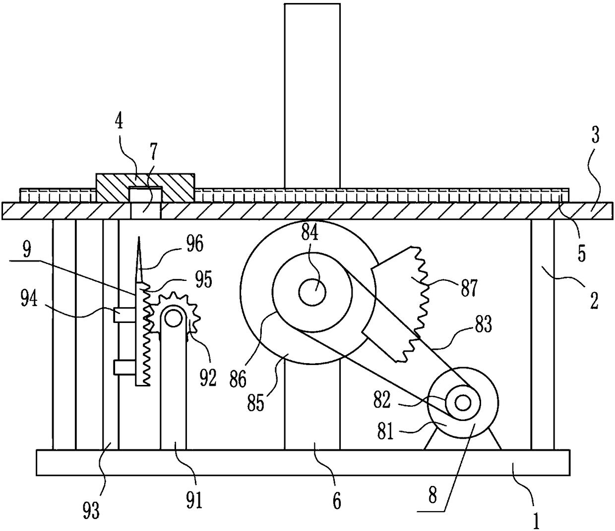
[0031] A device for evenly cutting plastic rods, such as Figure 1-5 As shown, it includes a bottom plate 1, a pole 2, a placement plate 3, an n-shaped frame 4, a vertical plate 6, a driving device 8 and a cutting device 9. A placement plate 3 is installed between the tops of the side struts 2, a through hole 7 is opened on the left side of the placement plate 3, an n-type frame 4 is installed on the left side of the top of the placement plate 3, the n-type frame 4 is located directly above the through hole 7, and the bottom plate 1 A vertical board 6 is installed in the middle of the top, and the vertical board 6 is located at the rear side of the placement board 3. A driving device 8 is provided between the right side of the top of the bottom board 1 and the lower part of the front side of the vertical board 6, and a cutting device 9 is provided on the left side of the top of the bottom board 1. The cutting part of the device 9 is located directly below the through hole 7 , ...

Embodiment 2

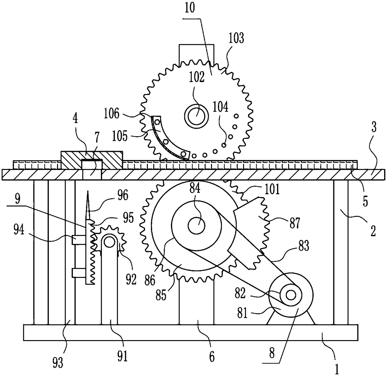
[0033] A device for evenly cutting plastic rods, such as Figure 1-5 As shown, it includes a bottom plate 1, a pole 2, a placement plate 3, an n-shaped frame 4, a vertical plate 6, a driving device 8 and a cutting device 9. A placement plate 3 is installed between the tops of the side struts 2, a through hole 7 is opened on the left side of the placement plate 3, an n-type frame 4 is installed on the left side of the top of the placement plate 3, the n-type frame 4 is located directly above the through hole 7, and the bottom plate 1 A vertical board 6 is installed in the middle of the top, and the vertical board 6 is located at the rear side of the placement board 3. A driving device 8 is provided between the right side of the top of the bottom board 1 and the lower part of the front side of the vertical board 6, and a cutting device 9 is provided on the left side of the top of the bottom board 1. The cutting part of the device 9 is located directly below the through hole 7 , ...

Embodiment 3

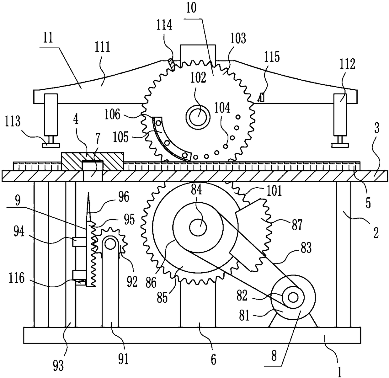
[0036] A device for evenly cutting plastic rods, such as Figure 1-5 As shown, it includes a bottom plate 1, a pole 2, a placement plate 3, an n-shaped frame 4, a vertical plate 6, a driving device 8 and a cutting device 9. A placement plate 3 is installed between the tops of the side struts 2, a through hole 7 is opened on the left side of the placement plate 3, an n-type frame 4 is installed on the left side of the top of the placement plate 3, the n-type frame 4 is located directly above the through hole 7, and the bottom plate 1 A vertical board 6 is installed in the middle of the top, and the vertical board 6 is located at the rear side of the placement board 3. A driving device 8 is provided between the right side of the top of the bottom board 1 and the lower part of the front side of the vertical board 6, and a cutting device 9 is provided on the left side of the top of the bottom board 1. The cutting part of the device 9 is located directly below the through hole 7 , ...


PUM


Abstract

The invention relates to cutting equipment, in particular to uniform plastic rod cutting equipment. The uniform plastic rod cutting equipment has the advantages that the time-saving and labor-saving effects are achieved, manual cutting is not needed, cuts are avoided, and cut plastic rods are uniform in length. The uniform plastic rod cutting device comprises a base plate and the like; supportingrods are symmetrically arranged on the left side and the right side of the top of the base plate; a placing plate is arranged between the top ends of the supporting rods on the left side and the rightside; a through hole is formed in the left side of the placing plate; an N-shaped frame is arranged on the left side of the top of the placing plate and is located right above the through hole; and avertical plate is arranged in the middle of the top of the base plate and is located on the rear side of the placing plate. According to the uniform plastic rod cutting equipment, by means of a fixing device, the plastic rods can be fixed in the cutting process, the phenomenon that the cutting effect is affected due to the fact that the plastic rods move can be avoided, and therefore the effectsthat time and labor are saved, manual cutting is not needed, the cuts are avoided, and the cut plastic rods are uniform in length can be achieved.

Description

technical field [0001] The invention relates to a cutting device, in particular to a uniform cutting device for plastic rods. Background technique [0002] Plastic is a high molecular compound polymerized by addition polymerization or polycondensation reaction with monomer as raw material. It is commonly known as plastic or resin. It can freely change its composition and shape. , Colorants and other additives. [0003] Before the plastic rod is used, the plastic rod will be cut to facilitate the use of the plastic rod. However, when the plastic rod is cut manually, it is time-consuming and laborious. It is easy to be cut by the cutter during the cutting process. The length of the cut plastic rod is the same. It is necessary to develop a time-saving and labor-saving device that cuts plastic rods evenly without being cut, and the length of the cut plastic rods is the same. Contents of the invention [0004] (1) Technical problems to be solved [0005] In order to overcome...

Claims


Application Information

Patent Timeline
Patent Type & Authority Applications(China)
IPC IPC(8): B26D1/06B26D5/08B26D7/02B26D7/06
Inventor 金吉祥谌小丽曾繁清
Owner 泗县东方塑料有限责任公司
Why Eureka
Try Eureka