Car seat with buffering equipment

A technology for car seats and buffer equipment, applied in vehicle seats, movable seats, vehicle parts, etc., can solve the problems of passenger collision, reduce the safety of passenger seats, avoid slippage, increase contact surface, The effect of protecting life safety

Inactive Publication Date: 2018-06-29
安徽久利昌机械有限公司
6 Cites 0 Cited by

AI-Extracted Technical Summary

Problems solved by technology

[0012] The purpose of the present invention is to provide a car seat equipped with a buffer device to solve the problem that in actual use, when the sliding rail locking device controlled by the pull r...

Method used

[0048] The setting of the matching groove 12 increases the contact surface between the ...

Abstract

The invention discloses a car seat with buffering equipment. The car seat comprises a car seat body, a base, seat sliding rails and a U-shaped pull rod which are connected in sequence; the car seat body is slidingly arranged on the seat sliding rails through the base, the tail ends of the pull rod are connected with the seat sliding rails respectively, and the pull rod controls the locking statesof locking devices of the seat sliding rails; the base is provided with a buffer assembly, the buffer assembly comprises a contact block, a connecting shaft, a movable plate, supporting shafts and a fixing plate, one end of the connecting shaft is connected with the contact block, the other end of the connecting shaft is connected with the movable plate, one end of each supporting shaft is connected with the fixing plate, the other end of each supporting shaft movably penetrates through the movable plate and is in threaded connection with a limiting nut, and each supporting shaft is sleeved with a spring. The contact block is in contact with the pull rod, the movable plate moves towards the base, the springs are gradually compressed, the movement speed of the car seat body is reduced, thenthe situation that a passenger hits a front object is avoided, and the life safety of the passenger is protected.

Application Domain

Technology Topic

Image

  • Car seat with buffering equipment
  • Car seat with buffering equipment
  • Car seat with buffering equipment

Examples

  • Experimental program(1)

Example Embodiment

[0038] Example 1
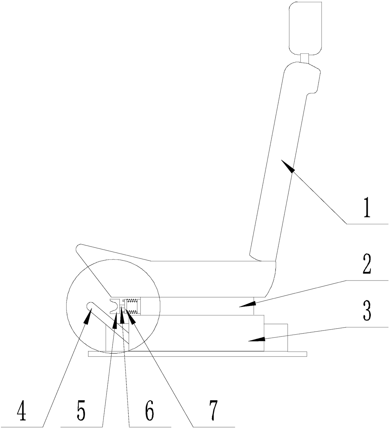
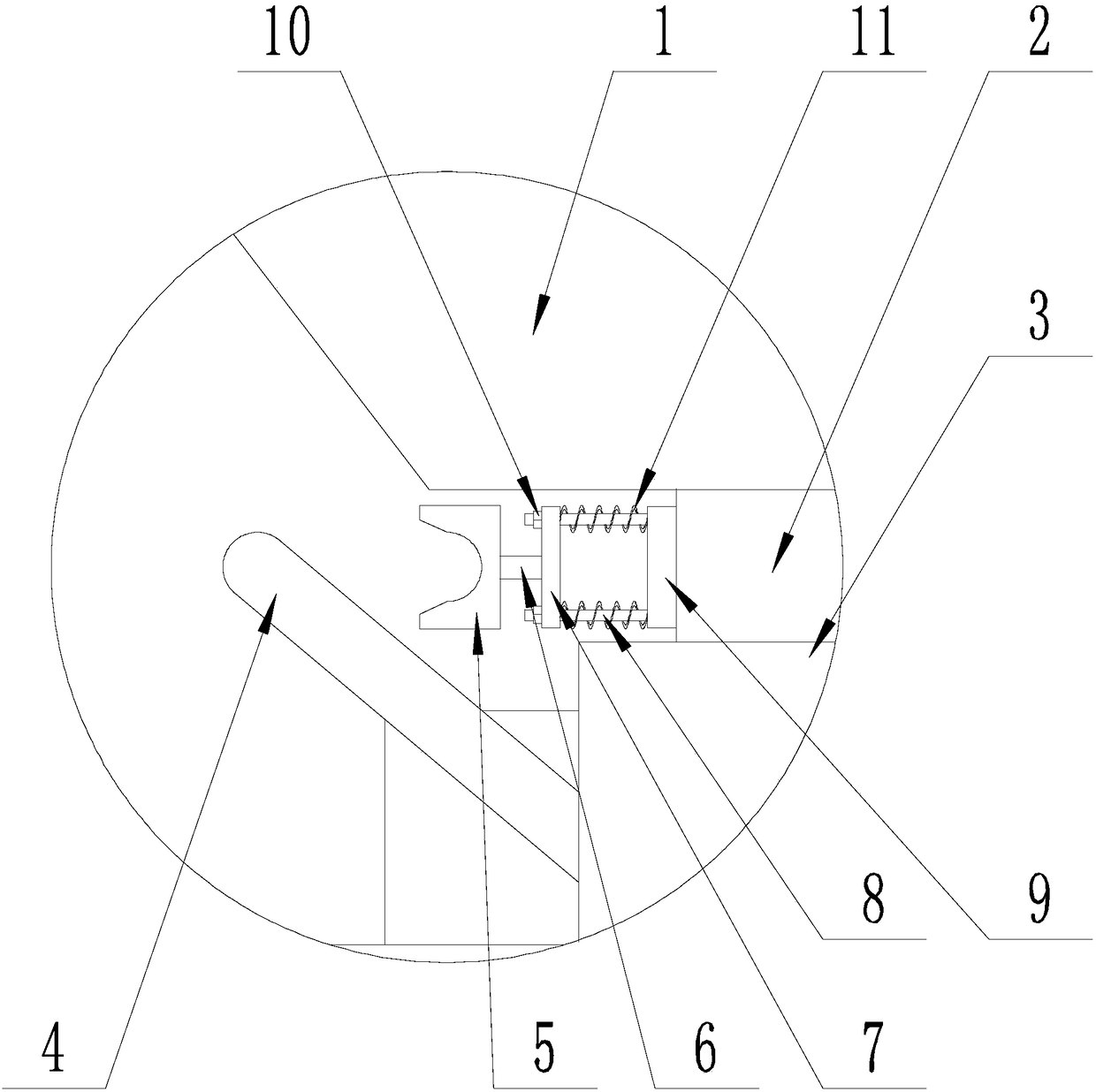
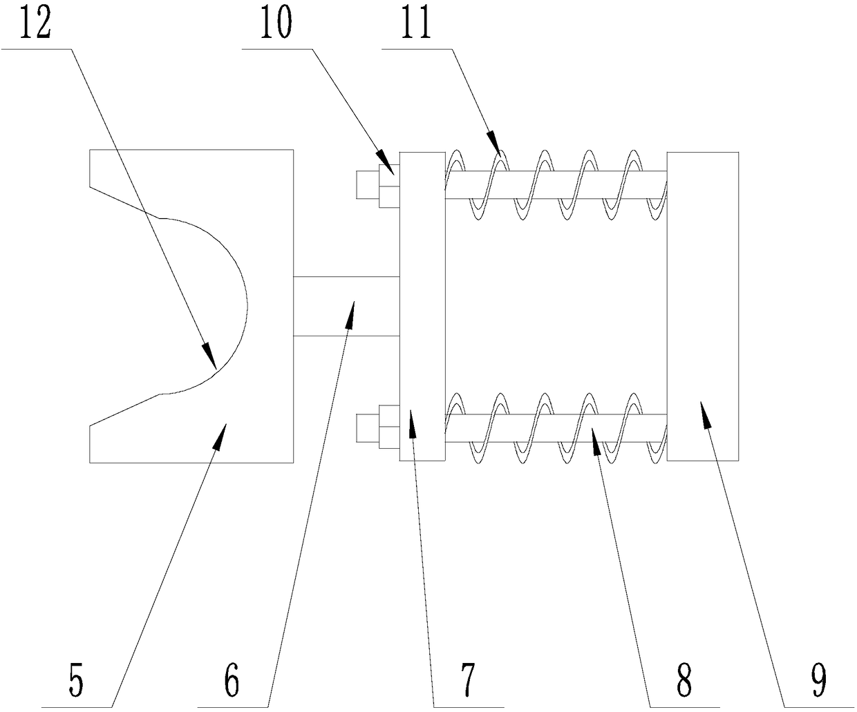
[0039] Such as Figure 1-Figure 3 As shown, the car seat provided with a cushioning device of the present invention includes a car seat body 1, a base 2, a seat slide rail 3, and a U-shaped pull rod 4 connected in sequence, and the car seat body 1 is slidably arranged by the base 2. On the seat slide rail 3, the ends of the pull rods 4 are respectively connected to a seat slide rail 3, and control the locking state of the locking device of the seat slide rail 3, which is close to the pull rod 4 on the base 2 One end of the connecting shaft is provided with a buffer assembly, which includes a contact block 5, a connecting shaft 6, a moving plate 7, a supporting shaft 8 and a fixed plate 9, which are connected in sequence. One end of the connecting shaft 6 is connected to the contact block 5, and the connecting shaft The other end of 6 is connected to the moving plate 7. One end of the supporting shaft 8 is connected to the fixed plate 9. The other end of the supporting shaft 8 movably penetrates the moving plate 7 and then is screwed to the limit nut 10, and there are several supporting shafts 8 , The axes are parallel to each other and parallel to the horizontal plane, and springs 11 are sleeved on the support shaft 8;
[0040] Moving the car seat body 1 along the seat slide 3 can make the contact block 5 contact the pull rod 4, push the moving plate 7 to move, and make the spring 11 in a compressed state.
[0041] When the slide rail locking device controlled by the pull rod 4 fails or the locking force is insufficient, causing the car seat body 1 to slide relative to the seat slide rail 3 due to inertia when the car suddenly brakes the car, the contact block 5 contacts the pull rod 4 , The moving plate 7 moves to the base 2, the spring 11 is gradually compressed, and the moving speed of the car seat body 1 is reduced, thereby preventing the passenger from hitting the object in front of it and protecting the life safety of the passenger.
[0042] When the seat needs to be slid forward for adjustment, pull the lever 4 upwards, then move the car seat body 1 forward, and then lower the lever 4. When the car seat body 1 is moved forward, when the contact block 5 is not in contact with the pull rod 4, when the car seat 1 is moved, only the friction between the base 2 and the slide rail 3 is overcome; when the contact block 5 contacts the pull rod 4, When moving the seat, it is necessary to overcome the friction between the base 2 and the slide rail 3 and the compression deformation force of the spring 11.
[0043] Preferably, the spring 11 is a cylindrical spiral compression spring.
[0044] Preferably, there are two supporting shafts 8.
[0045] The provision of two supporting shafts 8 enables the moving plate 7 to move only along the axis of the supporting shaft 8.
[0046] Further, the contact block 5 is provided with a matching groove 12 at the end contacting the pull rod 4, and the car seat body 1 is moved along the seat slide rail 3 so that the middle section of the pull rod 4 can be located in the matching groove 12 Contact with the groove bottom of the mating groove 12.
[0047] The pull rod 4 is U-shaped, which is composed of a straight section and vertical sections provided at both ends of the straight section, and the middle section is the straight section of the pull rod 4.
[0048] The arrangement of the matching groove 12 increases the contact surface between the pull rod 4 and the contact block 5 and prevents the contact block 5 from slipping.
[0049] Further, the opening size of the matching groove 12 is larger than the size of the groove bottom. The opening size of the fitting groove 12 is larger than the size of the groove bottom, so that the middle section of the tie rod 4 can be smoothly locked into the fitting groove 12.
[0050] Further, the groove bottom of the matching groove 12 is recessed into a semicircular shape, and when the draw rod 4 contacts the matching groove 12, the draw rod 4 and the groove bottom of the matching groove 12 are coaxial. In this way, the contact surface between the tie rod 4 and the matching groove 12 can be maximized, and the stability of the compression spring 8 can be improved.

PUM

no PUM

Description & Claims & Application Information

We can also present the details of the Description, Claims and Application information to help users get a comprehensive understanding of the technical details of the patent, such as background art, summary of invention, brief description of drawings, description of embodiments, and other original content. On the other hand, users can also determine the specific scope of protection of the technology through the list of claims; as well as understand the changes in the life cycle of the technology with the presentation of the patent timeline. Login to view more.

Similar technology patents

High-strength waterproof rock wool board preparation system

PendingCN114543506AReduce labor burdenProtect life safetyVertical furnacesIncrustation removal devicesSlagWool
Owner:王子蔚

Novel head drainage tube fixing device

PendingCN110559546APrevents the risk of accidental extubationProtect life safetyCatheterTube drawingEngineering
Owner:吉婷婷

Classification and recommendation of technical efficacy words

  • Increase contact surface
  • Protect life safety

Multifunctional double-channel welding line ultrasonic testing scanner

ActiveCN103529122AThe solution is not to swing in a steady stateIncrease contact surfaceAnalysing solids using sonic/ultrasonic/infrasonic wavesMultiple functionTransverse magnetic
Owner:BC P INC CHINA NAT PETROLEUM CORP +1

Dynamic thermal protection performance testing and evaluating device

InactiveCN104316562AProtect life safetyMaterial heat developmentHeat flux sensorHeat flow
Owner:ZHANGJIAGANG INST OF IND TECH SOOCHOW UNIV
Why Eureka
Try Eureka