
Building rescue information system

An information system and building technology, applied in the field of rescue information systems, can solve the problems of noisy personnel, difficulty in drilling continuity, difficulty in search and rescue, etc.

Inactive Publication Date: 2016-11-09
许耿祯
View PDF6 Cites 13 Cited by
  • Summary
  • Abstract
  • Description
  • Claims
  • Application Information

AI Technical Summary

Problems solved by technology

However, in the actual situation of the disaster area, the body of the survivors may have been bound by the narrow residual gap, and the hands and feet could no longer exert force to knock on the wall to make the sound of distress; secondly, the scene of the disaster area is chaotic and noisy, and it is difficult to keep the disaster area completely silent to listen to and identify the faint distress voices of survivors; moreover, although search and rescue teams can use optical fiber imaging equipment and infrared thermal imaging equipment to assist in disaster relief, it is often difficult to drill for continuity because survivors are trapped deep inside collapsed buildings. , a series of observation holes to place the above-mentioned auxiliary observation equipment in depth, resulting in the difficulty of actual search and rescue and the slow progress of search and rescue; finally, with limited search and rescue manpower and disaster relief resources, and under the pressure of the 72-hour golden rescue time limit, the on-site rescue commander needs to target the vast number of victims. The priority selection of search and rescue locations in the region, if the on-site rescue commander can be provided with relevant rescue information such as the number of people trapped on each floor of the building and the location of the trapped people, it will be able to assist him to make the most correct judgment

Method used


Image

  • Building rescue information system
  • Building rescue information system
  • Building rescue information system

Examples


Embodiment Construction

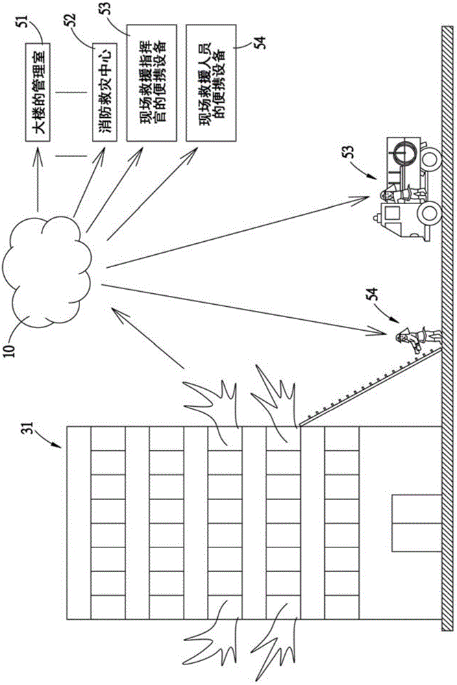
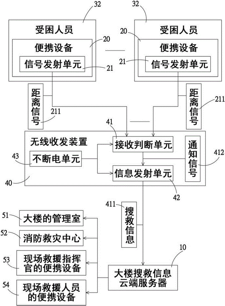
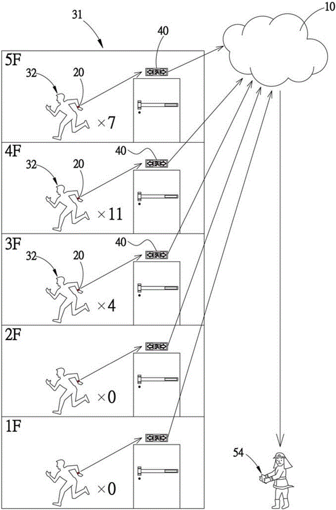
[0057] refer to Figure 1 to Figure 3 As shown, the building rescue information system provided by the first embodiment of the present invention is used in conjunction with the building search and rescue information cloud server 10 and a plurality of portable devices 20, and the portable devices 20 are installed on each floor of the building 31 for trapped persons 32, and has a signal transmitting unit 21 that can at least send out a distance signal 211; in this embodiment, the portable device 20 is a smart phone with a wireless network connection function, and can also be a wearable device, but not limited thereto. The building rescue information system includes:

[0058] A plurality of wireless transceivers 40 are arranged in the escape passage or the escape exit on each floor of the building 31, and have a receiving judgment unit 41 connected to the signal transmitting unit 21, and an information transmitting unit 41 connected to the receiving judging unit 41. Unit 42; in ...


PUM


Abstract

The invention provides a building rescue information system which comprises multiple wireless transceivers, wherein the wireless transceivers are disposed in escape channels or escape exits on each floor of a building. Each of the multiple wireless transceivers comprises a receiving and judgment unit connected to a signal transmitting unit, as well as an information transmitting unit which is in a signal connection with the receiving and judgment unit, wherein the receiving and judgment unit receives a distance signal sent by the signal transmitting unit, then judges at least the quantity of people trapped on each floor as well as search and rescue information of the locations, and converts the search and rescue information into a notification signal and transmits the signal to the information transmitting unit; and the information transmitting unit uploads the search and rescue information to a search and rescue information cloud side server of the building after receiving the notification signal, and continues updating the information. In this way, before rescue workers start off or when the rescue workers arrive at a disaster site of the building (under cases such as a fire or earthquake), the rescue workers can immediately master the accurate quantity of the people trapped on each floor as well as the trapping locations and take the information as an important reference basis for rescue priorities.

Description

technical field [0001] The invention relates to a rescue information system, in particular to a building rescue information system. Background technique [0002] Generally, the traditional fire detection systems installed on each floor of a building, such as smoke sensors, temperature sensors, or gas detectors, mainly notify the building through voice broadcasts when a fire is detected in the first place. If a fire breaks out, the personnel in the building are notified to escape as soon as possible. However, the fire escape exit indicator lights or escape direction indicator lights generally installed in the building can only statically guide the location of the safety doors on each floor in a fixed manner, but cannot guide them out. A safe escape route causes trapped people to escape to an unclear escape route, and it is easy to miss the golden escape time and be trapped in the building. [0003] However, when the rescuers arrive at the scene of the fire in the building, t...

Claims


Application Information

Patent Timeline
IPC IPC(8): H04L29/08H04W4/04H04W64/00G08B7/06G06Q50/26
CPCG06Q50/265G08B7/066H04L67/12H04W4/043H04W64/00
Inventor 许耿祯
Owner 许耿祯
Learn More