Wingtip rotor wing applied to unmanned aerial vehicle

A drone and wingtip technology, applied in the field of wingtip rotors, can solve the problems of complex rotor structure, weakening the lift of drones, reducing the stability of drones, etc., and achieve the effect of reducing weakening and induced drag

Inactive Publication Date: 2018-06-29
EWATT TECH CO LTD
View PDF7 Cites 2 Cited by
  • Summary
  • Abstract
  • Description
  • Claims
  • Application Information

AI Technical Summary

Problems solved by technology

[0005] The technical problem to be solved by the present invention is that the structure of the rotor is complicated, and the daily maintenance is not convenient; and the wing tip will weaken the lift of the UAV and reduce the stability of the UAV.

Method used


Image

  • Wingtip rotor wing applied to unmanned aerial vehicle
  • Wingtip rotor wing applied to unmanned aerial vehicle
  • Wingtip rotor wing applied to unmanned aerial vehicle

Examples


Embodiment Construction

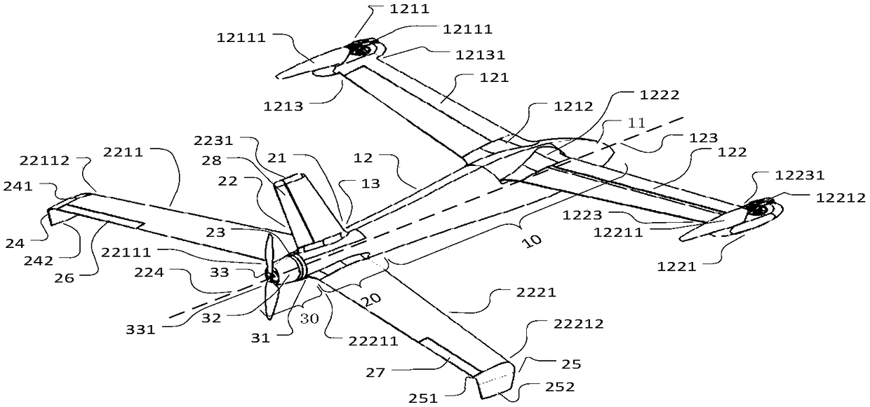
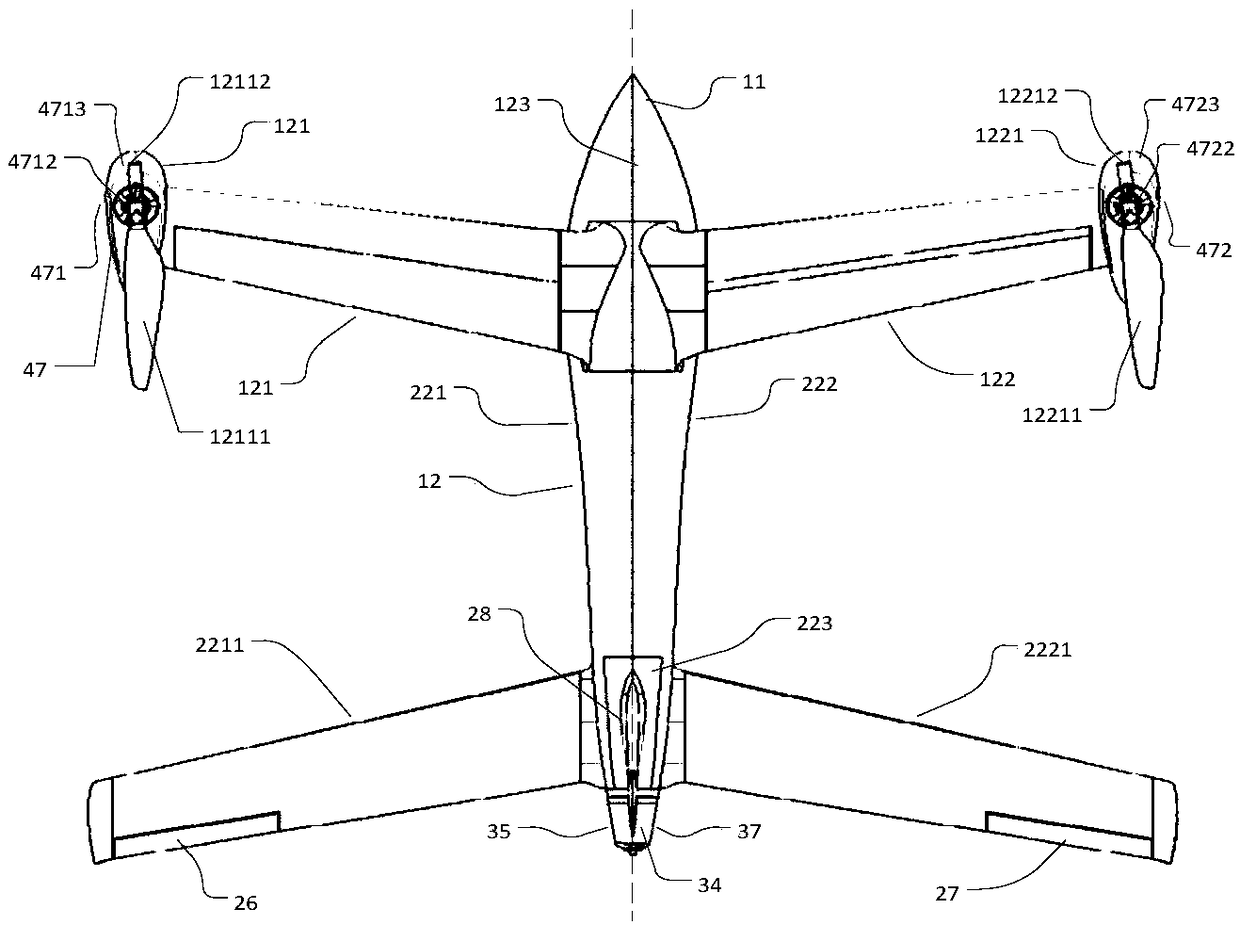
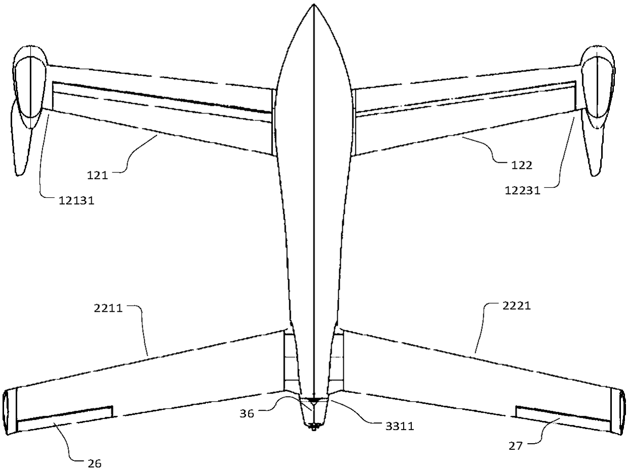
[0027] The invention discloses a wingtip rotor applied to an unmanned aerial vehicle. The first rotating blade and the first counterweight are respectively fixedly connected to the first rotor shaft so that the first rotating blade and the first counterweight are relative to the first The rotor shafts are symmetrically distributed, and the first rotor shaft is perpendicular to the rotation plane of the first rotating blade; the second rotating blade and the second counterweight are fixedly connected to the second rotor shaft respectively, so that the second rotating blade and the second counterweight The blocks are distributed symmetrically with respect to the second rotor axis, which is perpendicular to the plane of rotation of the second rotary blade. At the same time, by fixedly connecting the first wingtip fastening end with the first rear opening end, the first wingtip opening end of the first winglet deviates from the first rear opening end, and is fastened to the first w...


PUM


Abstract

The invention discloses a wingtip rotor wing applied to an unmanned aerial vehicle, belonging to the technical field of unmanned aerial vehicles. The wingtip rotor wing comprises a first rotor wing, and a first rotating blade of the first rotor wing is fixedly connected with a first rotor wing shaft of a steering engine; a first weight balancing block is fixedly connected with the first rotor wingshaft, and the first rotating blade and the first weight balancing block are symmetrically arranged relative to the first rotor wing shaft; a second rotating blade of a second rotor wing is fixedly connected with a second rotor wing shaft of the steering engine; the second weight balancing block is fixedly connected with the second rotor wing shaft, and the second rotating blade and the second weight balancing block are symmetrically arranged relative to the second rotor wing shaft. Meanwhile, a first wingtip small wing is intersected with a first rear arranged wing; a first wingtip fasteningend is fixedly connected with a first rear opening end; a second wingtip small wing is intersected with a second rear arranged wing; and a second wingtip fastening end of the second wingtip small wing is fixedly connected with a second rear opening end. The wingtip rotor wing has the technical effects that a rotor wing structure is simplified, daily maintenance is convenient, and the stability ofthe unmanned aerial vehicle is improved.

Description

technical field [0001] The invention belongs to the technical field of unmanned aerial vehicles, in particular to a wingtip rotor applied to unmanned aerial vehicles. Background technique [0002] Unmanned UAV, referred to as "UAV", is an unmanned UAV controlled by radio remote control equipment and its own program control device. The rotor is the main lift component of the UAV. During the flight of the UAV, the rotor plays a role in generating lift. [0003] Currently, rotors are made up of multiple (more than 2) blades, and as the blades in the rotor rotate, the blades will interact with the surrounding air, creating a pulling force along the rotor axis that will give the aircraft an upward movement of lift. By adjusting the rotation speed of the blades, the magnitude of the lift is controlled, so that the aircraft can take off and land. The wingtip of the drone is mainly directly formed by one end of the wing. When maintaining normal flight, the UAV relies on the pres...

Claims


Application Information

Patent Timeline
Patent Type & Authority Applications(China)
IPC IPC(8): B64C27/32B64C3/10B64C27/08
CPCB64C27/32B64C3/10B64C27/08
Inventor 赵国成漆鹏程罗伟
Owner EWATT TECH CO LTD
Why Eureka
Try Eureka