Capacitor electric core placing device

A technology for capacitors and batteries, which is applied in the field of capacitor battery swinging devices, and can solve problems such as low production efficiency

Pending Publication Date: 2018-06-29
SHENZHEN CHENGJIE INTELLIGENT EQUIP CO LTD
View PDF0 Cites 4 Cited by
  • Summary
  • Abstract
  • Description
  • Claims
  • Application Information

AI Technical Summary

Problems solved by technology

[0003] Based on this, it is necessary to provide a capacitor cell swinging device for th

Method used


Image

  • Capacitor electric core placing device
  • Capacitor electric core placing device
  • Capacitor electric core placing device

Examples


Embodiment Construction

[0027] In order to facilitate the understanding of the present invention, the present invention will be described more fully below with reference to the associated drawings. Preferred embodiments of the invention are shown in the accompanying drawings. However, the present invention can be embodied in many different forms and is not limited to the embodiments described herein. On the contrary, these embodiments are provided to make the understanding of the disclosure of the present invention more thorough and comprehensive.

[0028] Unless otherwise defined, all technical and scientific terms used herein have the same meaning as commonly understood by one of ordinary skill in the technical field of the invention. The terminology used herein in the description of the invention is for the purpose of describing specific embodiments only, and is not intended to limit the present invention. As used herein, the term "and / or" includes any and all combinations of one or more of the ...


PUM


Abstract

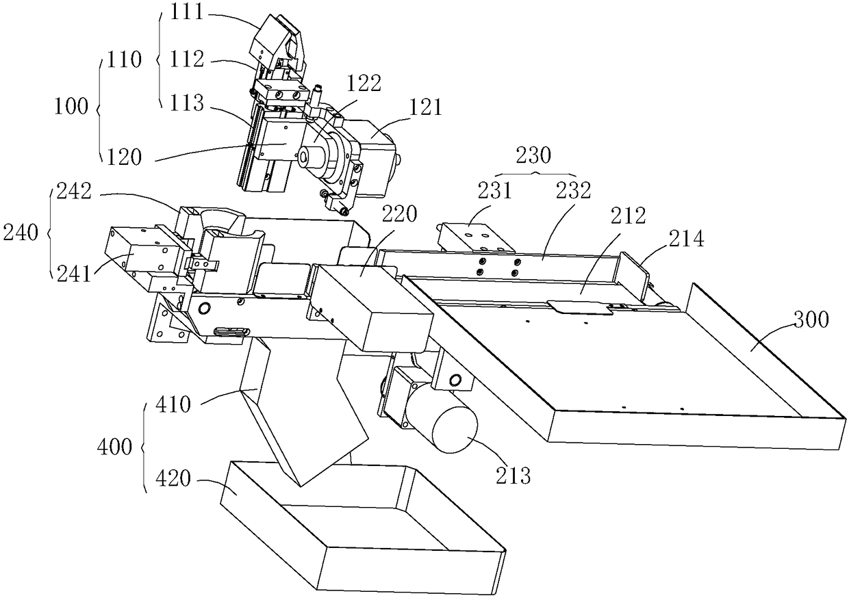
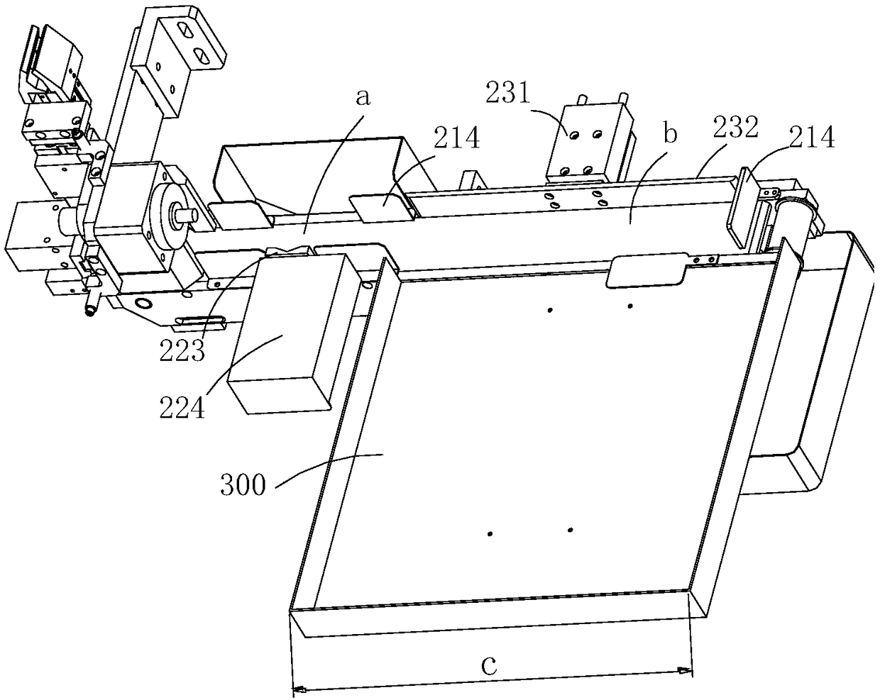
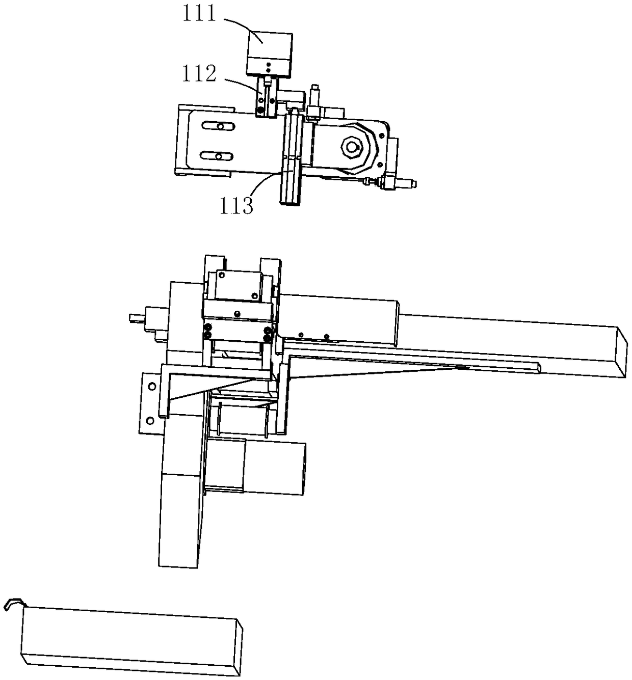
The invention relates to a capacitor electric core placing device. The capacitor electric core placing device comprises a clamping mechanism, a conveying control mechanism, a qualified product holdingmechanism and an unqualified product holding mechanism. The clamping mechanism places electric cores obtained after winding onto the conveying control mechanism. The unqualified product holding mechanism is connected with the structure, located on a first conveying portion, of the conveying control mechanism, and the qualified product holding mechanism is connected with the structure, located ona second conveying portion, of the conveying control mechanism. The extending direction of the qualified product holding mechanism is perpendicular to the conveying direction of the conveying controlmechanism. After receiving the electric cores, the conveying control mechanism places the unqualified electric cores into the unqualified product holding mechanism and conveys the qualified electric cores to the second conveying portion in sequence; and after the second conveying portion is full of the electric cores, the conveying control mechanism simultaneously pushes the electric cores on thesecond conveying portion into the qualified product holding mechanism in the direction perpendicular to the conveying direction, and the relative positions of all the electric cores are kept unchanged. The capacitor electric core placing device can improve production efficiency.

Description

technical field [0001] The invention relates to the technical field of capacitor manufacturing, in particular to a capacitor cell swinging device. Background technique [0002] As one of the basic electronic components, capacitors are widely used in the electronic industry such as household appliances, displays, lighting appliances, communication products and other electronic equipment. In the manufacturing process of capacitors, after the winding is completed, the cells need to be placed in the tray. However, the battery cells placed in the tray are usually in a disorderly state, and the battery cells need to be arranged neatly manually before entering the next process, thereby reducing production efficiency. Contents of the invention [0003] Based on this, it is necessary to provide a capacitor cell swinging device for the problem of low production efficiency in the traditional capacitor manufacturing process. [0004] A capacitor battery swinging device, including a ...

Claims


Application Information

Patent Timeline
IPC IPC(8): B65G47/90B65G47/04B65G47/74B65G47/26
CPCB65G47/04B65G47/26B65G47/74B65G47/90B65G2201/0214
Inventor 陈汉廷刘孙根谭国彪
Owner SHENZHEN CHENGJIE INTELLIGENT EQUIP CO LTD
Why Eureka
Try Eureka