Lifting device special for large steel plates

A kind of steel plate, large-scale technology, applied in the field of large-scale steel plate special hangers

Active Publication Date: 2018-06-29
佛山市顺德区森焱五金制品有限公司
View PDF5 Cites 1 Cited by
  • Summary
  • Abstract
  • Description
  • Claims
  • Application Information

AI Technical Summary

Problems solved by technology

[0003] Currently, there is

Method used


Image

  • Lifting device special for large steel plates
  • Lifting device special for large steel plates
  • Lifting device special for large steel plates

Examples


Embodiment Construction

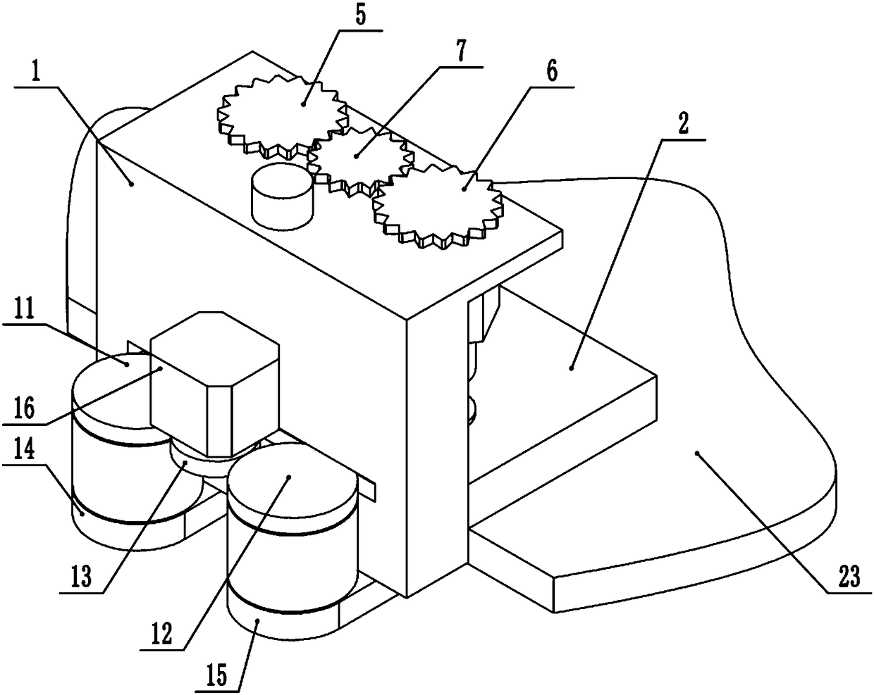
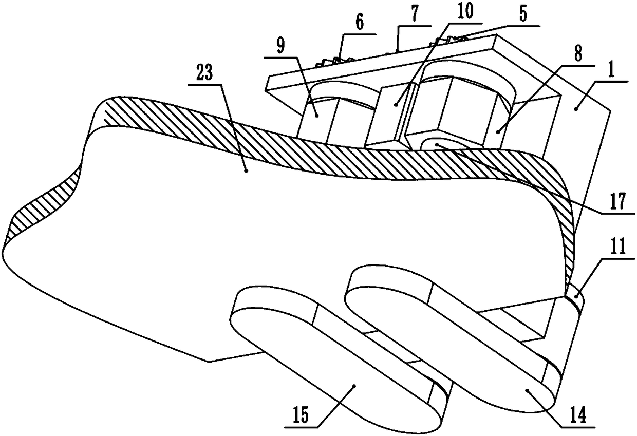
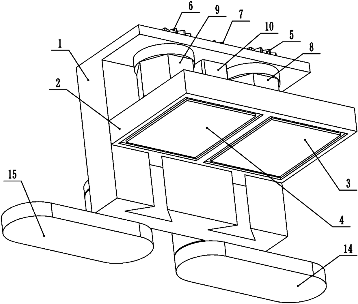
[0019] A special spreader for large steel plates is composed of a frame 1, a pressure plate 2, a first electromagnet 3, a second electromagnet 4, a first driven gear 5, a second driven gear 6, a first driving gear 7, a second Lead screw slider 8, the second lead screw slider 9, the first motor 10, the first driven circular wheel 11, the second driven circular wheel 12, the first driving circular wheel 13, the first supporting plate 14, the first Two pallets 15, the second motor 16, the first lead screw 17, the second lead screw 18, the first shell 19, the second shell 20, the third shell 21 and the suspension ring 22, the frame 1 is structurally It includes main frame 101, first mounting hole 102, second mounting hole 103, third mounting hole 104, first dovetail groove 105, second dovetail groove 106, fourth mounting hole 107, fifth mounting hole 108, frame The upper surface 109, the lifting ring protrusion 110, the inner facade 111 of the frame, the round wheel groove 112 and...


PUM


Abstract

The invention relates to a lifting device special for large steel plates, and belongs to the field of hoisting tools. Specifically, the device adopts electromagnet adsorption, and a clamp clamps the edges of the steel plates, so that hoisting is facilitated. The multiple lifting devices are used simultaneously, the safety is improved more greatly, and the work efficiency is improved; the steel plates do not make direct contact with steel wire ropes in the hoisting process, abrasion and strand breaking of the steel wire ropes are avoided, the service life of the steel wire ropes is prolonged, and the potential safety hazards are eliminated; in the hoisting process, the lifting device applies certain locking force on the steel plates, the steel plates are not likely to slide, and the hoisting process is stable and safe; and the overall structure is compact, operation is convenient, safe and fast, the working intensity of workers is reduced, and the personal safety of the workers is ensured.

Description

technical field [0001] The invention relates to a special hoisting tool for large steel plates, specifically a device that adopts electromagnet adsorption and clamps the edge of the steel plate to facilitate hoisting, and belongs to the field of hoisting tools. Background technique [0002] Generally, industrial and mining enterprises directly use wire ropes to lift thicker steel plates. The traditional lifting method is to pass more than two wire ropes through the lower surface of the steel plate, and then hang the ends of the wire ropes on the crane hook for lifting. During the lifting process, the steel wire rope wears at the edges and corners of the steel plate edge, which is prone to broken strands and shortens the service life of the steel wire rope. Moreover, because the force direction of the force point of the steel wire rope on the edge of the steel plate is different from the lifting direction, the resulting force makes the steel wire rope move towards the middle...

Claims


Application Information

Patent Timeline
IPC IPC(8): B66C1/06B66C1/44
CPCB66C1/06B66C1/445
Inventor 高壮壮由子浩王文娇
Owner 佛山市顺德区森焱五金制品有限公司
Why Eureka
Try Eureka