Commutator assembling machine and commutator assembling method thereof

A commutator and assembly machine technology, which is applied to assembly machines, metal processing, metal processing equipment, etc., can solve problems such as low assembly efficiency, low product yield, and poor installation accuracy of pole pieces, and achieve high assembly efficiency and compact size. small, simple structure

Active Publication Date: 2019-07-19
UNIV OF ELECTRONICS SCI & TECH OF CHINA ZHONGSHAN INST
View PDF12 Cites 5 Cited by
  • Summary
  • Abstract
  • Description
  • Claims
  • Application Information

AI Technical Summary

Problems solved by technology

At present, the above-mentioned components are usually assembled together manually, and the assembly efficiency is low; although some assembly machines related to the commutator have also appeared, these assembly machines have complex structures, difficult control, poor installation accuracy of pole pieces, and the upper and lower The tripod is easy to break during material processing, and the product yield rate is low in actual production

Method used


Image

  • Commutator assembling machine and commutator assembling method thereof
  • Commutator assembling machine and commutator assembling method thereof
  • Commutator assembling machine and commutator assembling method thereof

Examples


Embodiment Construction

[0050] The present invention will be further described below in conjunction with accompanying drawing:

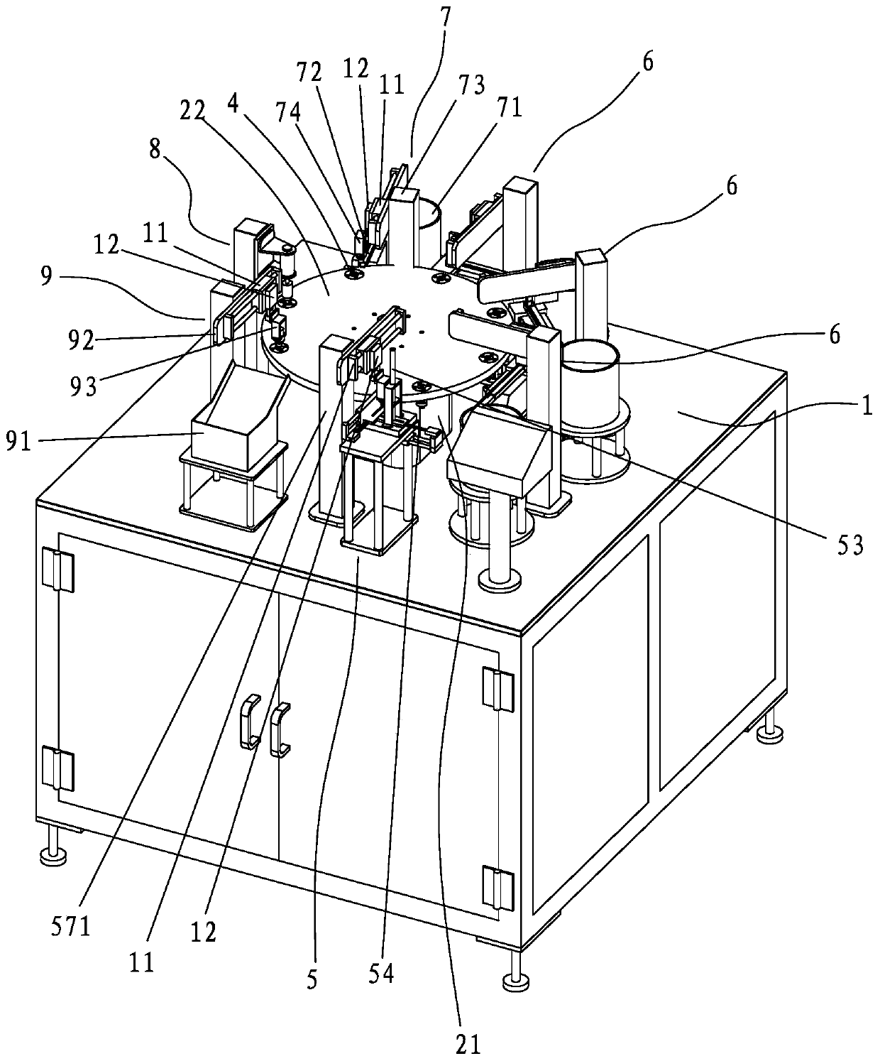
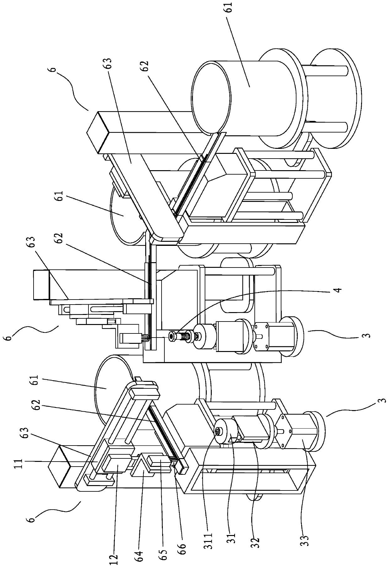
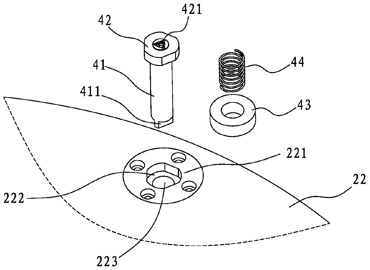
[0051] Such as Figure 1 to Figure 13 A commutator assembly machine shown includes an assembly platform 1, on which a divider 21 and a turntable 22 are arranged, and the divider 21 drives the turntable 22 to rotate intermittently, and the turntable 22 is arranged along the circumference A plurality of tooling 4 for clamping is evenly placed, and the assembly table 1 is located on the outer side of the turntable 22 along the circumference of the turntable 22, and is sequentially provided with a pressure ring feeding structure 5 and a plurality of pole piece feeding structures. Mechanism 6, skeleton feeding mechanism 7, skeleton pressing mechanism 8 and commutator unloading mechanism 9, the pressure ring feeding structure 5 is used to put the pressure ring 101 into the tooling 4, and a plurality of pole piece feeding The mechanism 6 is arranged from front to back around the ...


PUM


Abstract

The invention discloses a commutator assembling machine and a commutator assembling method thereof. The commutator assembling machine is characterized in that a divider and a turntable are arranged onan assembling table; a plurality of tools are uniformly arranged on the turntable in the circumferential direction; a pressure ring feeding structure, a plurality of pole piece feeding mechanisms, aframework feeding mechanism, a framework pressing mechanism and a commutator discharging mechanism are sequentially arranged on the outer side of the turntable from front to back in the circumferential direction; and a rotating mechanism used for driving the tools above to rotate relative to the turntable when the turntable stops rotating is arranged below the turntable. The method comprises the steps: pressing rings are placed into the tools through the pressing ring feeding structure, the turntable rotates to rotate the pressing rings to the first pole piece feeding mechanism to be loaded with a first pole piece, then to the next pole piece feeding mechanism, the position, with no pole piece, on each pressing ring is driven by the rotating mechanism to rotate to an assembling position tobe loaded with a pole piece, the pressing rings are sequentially rotated downwards till all the pole pieces are installed, and after a framework is installed through the framework loading mechanism and the framework pressing mechanism, the commutator discharging mechanism removes a commutator from the tools. The assembling efficiency is high.

Description

[0001] 【Technical field】 [0002] The invention relates to a commutator assembly machine, and the invention also relates to a method for assembling a commutator. [0003] 【Background technique】 [0004] A commutator is a component used for electrical signal switching, such as Figure 14 and Figure 15 , the commutator 100 includes a pressure ring 101, three pole pieces 102 and a frame 103, wherein the pole pieces are made of metal for the transmission of electrical signals, the pressure ring and the frame are usually made of non-conductive materials, such as engineering plastics, pole pieces The piece is composed of the pole piece fixing part 1021 inserted into the pressure ring and the pole piece bending part 1022 bent outward along the pressure ring. The three pole piece fixing parts are inserted into the pressure ring at intervals and evenly pasted in the pressure ring On the hole, the skeleton includes a skeleton tightening part 1031 and a skeleton pressing part 1032, and ...

Claims


Application Information

Patent Timeline
Patent Type & Authority Applications(China)
IPC IPC(8): B23P21/00
CPCB23P21/006B23P19/001Y02E60/10
Inventor 祝胜光李江
Owner UNIV OF ELECTRONICS SCI & TECH OF CHINA ZHONGSHAN INST
Why Eureka
Try Eureka