Angle adjustable cutting device for plastic-steel door and window machining

A technology of plastic steel doors and windows and cutting device, which is applied in metal processing and other directions, can solve the problems of inability to buffer, affect cutting accuracy, and large errors, and achieve the effect of preventing breakage and improving stability.

Inactive Publication Date: 2019-03-26
安徽名特玻璃有限公司
View PDF1 Cites 7 Cited by
  • Summary
  • Abstract
  • Description
  • Claims
  • Application Information

AI Technical Summary

Problems solved by technology

[0002] In the prior art: the patent application publication number CN 207044229U discloses an adjustable angle cutting device for processing plastic-steel doors and windows, including a bottom plate, four legs are arranged on the upper surface of the bottom plate, and the upper surface of the legs is A workbench is provided, and a servo motor is provided on the upper surface of the workbench close to the front side. The output shaft of the servo motor is connected with a mounting bracket, which is easy to damage the device during cutting, and cannot be damped, which will affect the cutting accuracy. Comparing the angle between the cutting device and the plastic-steel doors and windows leads to large errors and cannot be buffered. It cannot prevent the cutting device from breaking and getting stuck on the plastic-steel doors and windows caused by excessive cutting. The fixing ability of the plastic-steel doors and windows is poor, and iron filings are easy to get stuck device gap

Method used


Image

  • Angle adjustable cutting device for plastic-steel door and window machining
  • Angle adjustable cutting device for plastic-steel door and window machining
  • Angle adjustable cutting device for plastic-steel door and window machining

Examples


Embodiment Construction

[0024] The following will clearly and completely describe the technical solutions in the embodiments of the present invention with reference to the accompanying drawings in the embodiments of the present invention. Obviously, the described embodiments are only some, not all, embodiments of the present invention. Based on the embodiments of the present invention, all other embodiments obtained by persons of ordinary skill in the art without making creative efforts belong to the protection scope of the present invention.

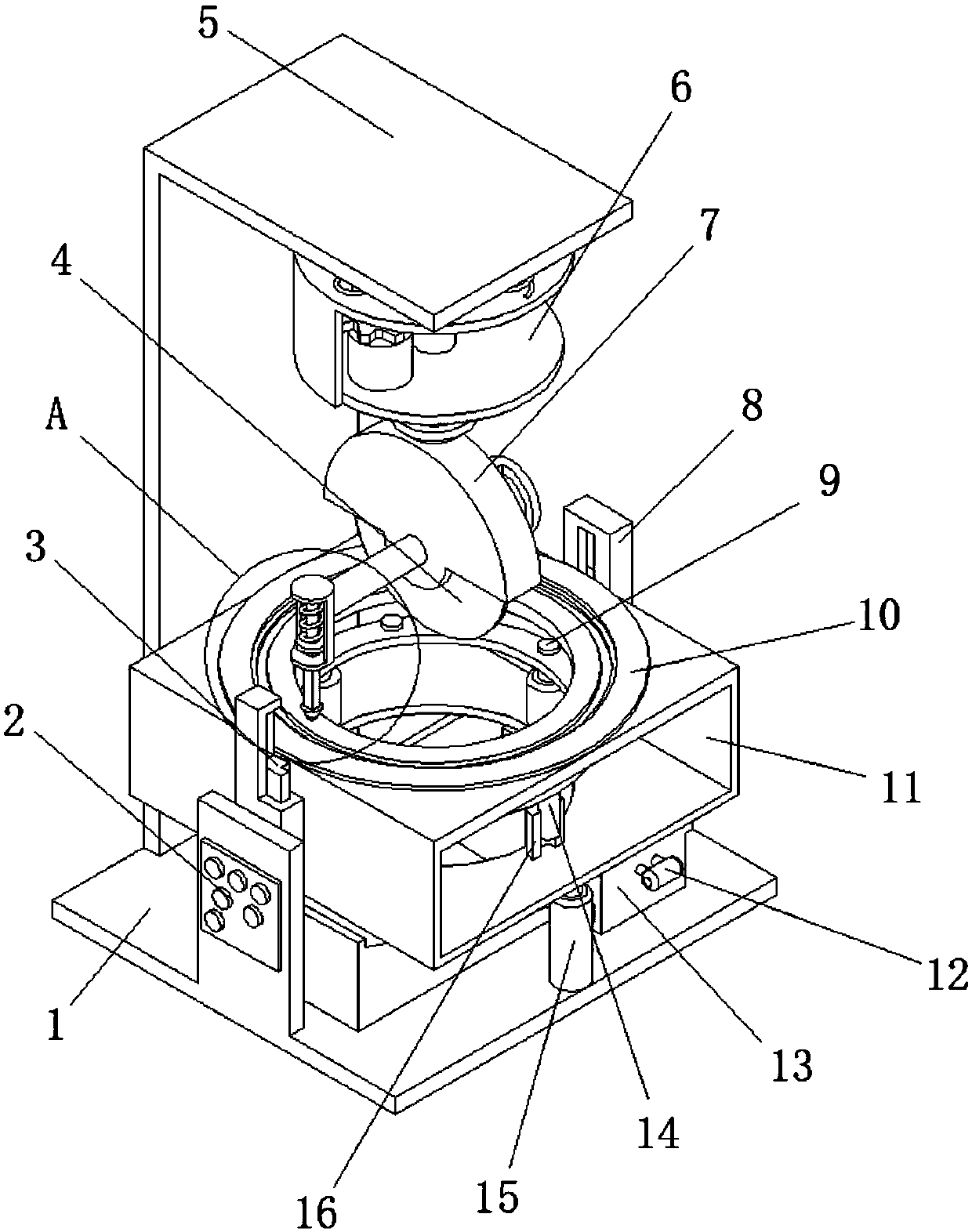
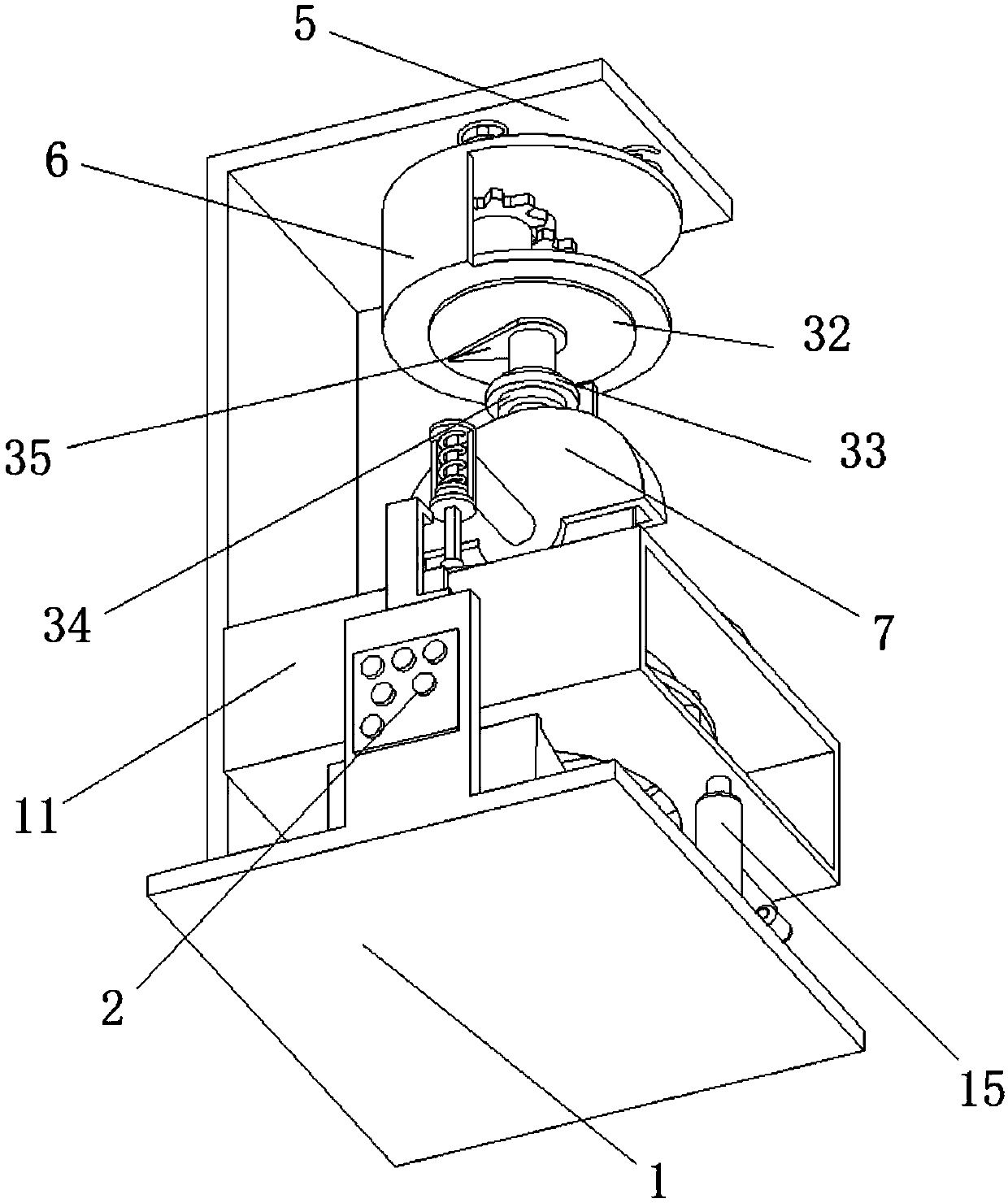
[0025] see Figure 1-4, the present invention provides a technical solution: an adjustable angle cutting device for processing plastic-steel doors and windows, including a base 1, and the sides of the vertical protruding plates at the left and right ends of the base 1 are provided with T-shaped slide rails 8, and the base The front and rear ends of the top of 1 are respectively connected to the fixed ends of two parallel electric telescopic rods-15, and the te...


PUM


Abstract

The invention discloses an angle adjustable cutting device for plastic-steel door and window machining. The angle adjustable cutting device for plastic-steel door and window machining comprises a base. The sides, close to each other, of vertical extending plates at the left end and the right end of the base are both provided with T-shaped sliding rails. The front end and the rear end of the top ofthe base are connected with fixed ends of two parallel first electric extensible and retractable rods correspondingly. The extensible and retractable ends of the two first electric extensible and retractable rods are connected with the front end and the rear end of the bottom of a fixing chamber correspondingly. The left side and the right side of the fixing chamber are provided with T-shaped sliding strips which are vertically distributed. The two T-shaped sliding strips are in sliding connection with the two T-shaped sliding rails correspondingly. According to the angle adjusting cutting device, the situation that a plastic-steel door and window deviates during machining, and the cutting angle is changed can be prevented, meanwhile, a pointer rotates, the rotation angle can be determined, angle contrasting can be carried out, defective materials can be prevented from dropping out and are cleaned conveniently, the stability of the device is improved, buffering is carried out, a cutting piece can be prevented from excessively cutting into the plastic-steel door and window, and then the situation the cutting device is fractured and clamped on the plastic-steel door and window is prevented.

Description

technical field [0001] The invention relates to the technical field of processing devices for plastic-steel doors and windows, in particular to an angle-adjustable cutting device for processing plastic-steel doors and windows. Background technique [0002] In the prior art: the patent application publication number CN 207044229U discloses an adjustable angle cutting device for processing plastic-steel doors and windows, including a bottom plate, four legs are arranged on the upper surface of the bottom plate, and the upper surface of the legs is A workbench is provided, and a servo motor is provided on the upper surface of the workbench close to the front side. The output shaft of the servo motor is connected with a mounting bracket, which is easy to damage the device during cutting, and cannot be damped, which will affect the cutting accuracy. Comparing the angle between the cutting device and the plastic-steel doors and windows leads to large errors and cannot be buffered....

Claims


Application Information

Patent Timeline
IPC IPC(8): B26D1/16B26D5/08B26D7/02B26D7/18B26D7/27B26D7/00
CPCB26D1/16B26D5/086B26D7/00B26D7/02B26D7/18B26D7/27B26D2007/0018
Inventor 周鑫炎
Owner 安徽名特玻璃有限公司
Why Eureka
Try Eureka