Automatic coating device

A paint and equipment technology, applied in the field of automatic paint equipment, can solve the problems of paint spilling on the ground, low work efficiency, uneven application, etc., and achieve the effects of reducing labor, improving work efficiency, and brushing parts uniformly

Active Publication Date: 2020-08-11
吴璐纯
View PDF12 Cites 8 Cited by
  • Summary
  • Abstract
  • Description
  • Claims
  • Application Information

AI Technical Summary

Problems solved by technology

[0002] At present, large-scale coating is required on the bottom plate of the cooling tower, and glass fiber needs to be laid on the side of the coating. The existing one needs to be manually controlled, and the labor consumption is large, and the coating is uneven, and a large amount of coating will be spilled on the ground. Resources waste, which also leads to inefficiency

Method used


Image

  • Automatic coating device
  • Automatic coating device
  • Automatic coating device

Examples


Embodiment Construction

[0029] In order to enable those in the technical field to better understand the solutions of the present invention, the technical solutions in the embodiments of the present invention will be clearly and completely described below in conjunction with the drawings in the embodiments of the present invention.

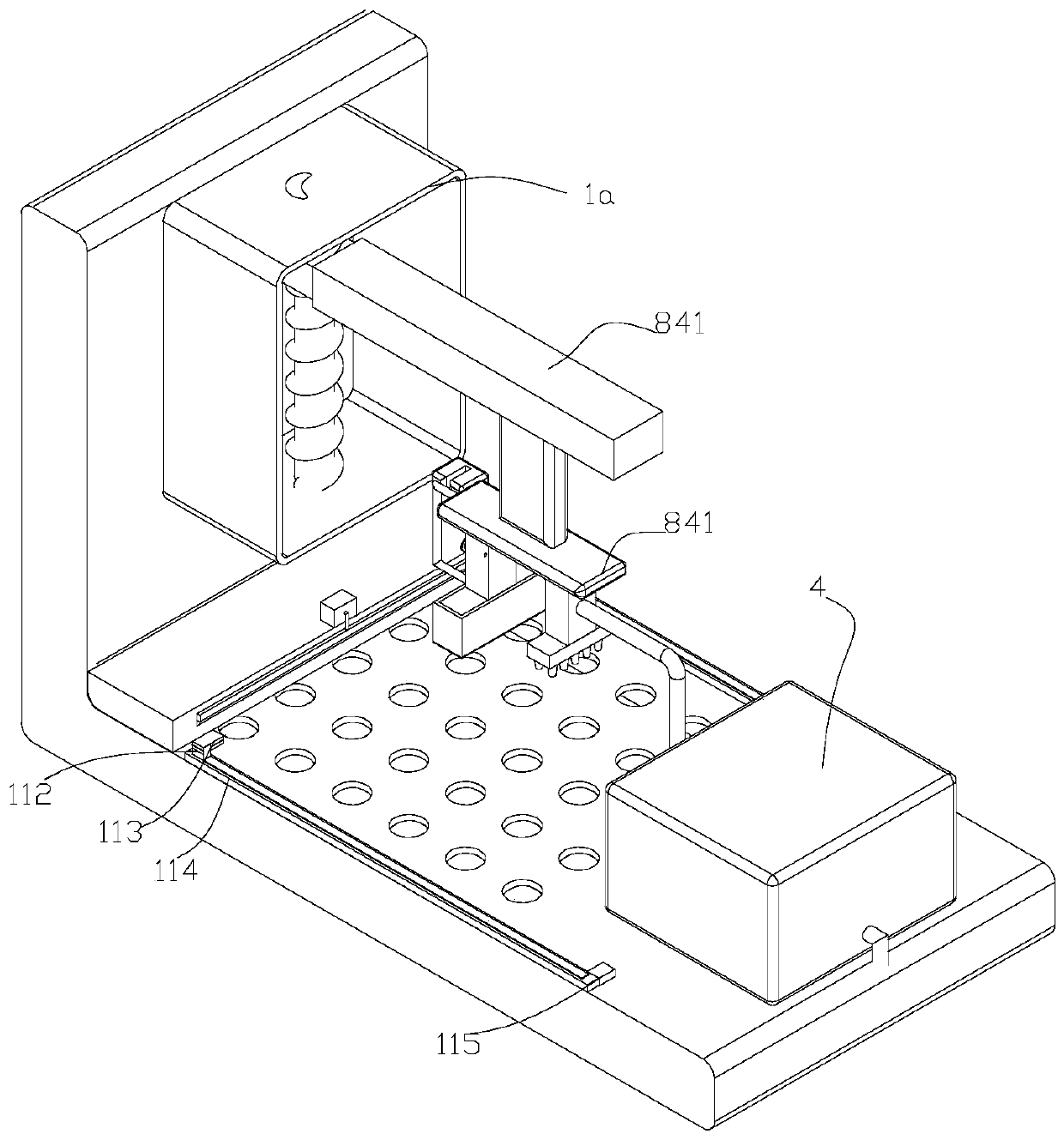
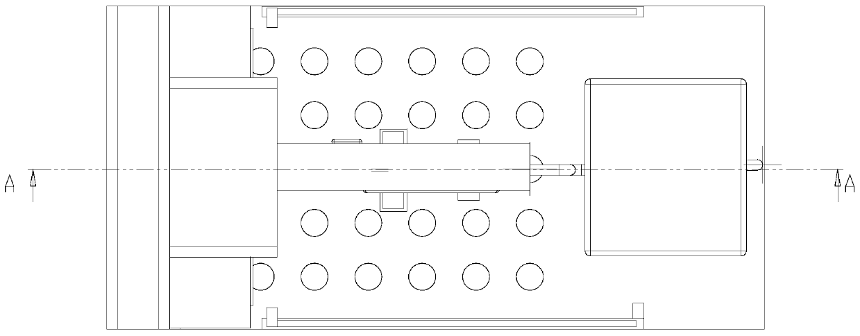
[0030]As shown in the figure, a kind of automatic coating equipment comprises vertical plate 1, base plate 2, distribution box 3, paint box 4, paint recovery box 5, paint mechanism 6, cutting mechanism 7, moving mechanism 8 and moving box 1a; The bottom plate 2 is fixedly connected to the upper part of the vertical plate 1, and a plurality of mesh holes are opened on the bottom plate 2; the distribution box 3 is fixedly connected at the angle between the vertical plate 1 and the bottom plate 2; The right side; the paint recovery box 5 is located inside the base plate 2; the mobile box 1a is fixedly connected to the upper right side of the vertical plate 1; the paint mechan...


PUM


Abstract

The invention discloses an automatic coating device. The automatic coating device comprises a vertical plate, a transverse plate arranged at the lower portion of the vertical plate, a material distribution box arranged on the left side of the upper portion of the transverse plate, a coating box arranged on the right side of the upper portion of the transverse plate, a coating recycling box arranged in the transverse plate, a moving box arranged on the right side of the vertical plate, a moving mechanism arranged in the moving box, a coating mechanism arranged in the coating box, and a cutting-off mechanism arranged on the material distribution box. The automatic coating device is characterized in that the moving mechanism comprises a first motor, a first screw rod arranged at the upper portion of the first motor, a first nut arranged at the outer portion of the first screw rod in a sleeving manner, and a lifting part arranged on the right side of the first nut, wherein the first nut can move vertically on the first screw rod.

Description

technical field [0001] The invention belongs to the technical field of coating equipment, in particular to an automatic coating equipment. Background technique [0002] At present, large-scale coating is required on the bottom plate of the cooling tower, and glass fiber needs to be laid on the side of the coating. The existing one needs to be manipulated manually, the labor consumption is large, and the coating is uneven, and a large amount of coating will be spilled on the ground. Resources Waste also leads to low work efficiency. Contents of the invention [0003] In order to overcome the deficiencies of the prior art, the present invention provides an automatic coating machine with high degree of automation, labor cost saving and reasonable recycling of resources. [0004] In order to achieve the above object, the present invention adopts the following technical solutions: an automatic coating equipment, including a vertical plate, a horizontal plate located at the low...

Claims


Application Information

Patent Timeline
Patent Type & Authority Applications(China)
IPC IPC(8): B05C1/02B05C11/10B05B13/02B05B13/04B05B14/00D06H7/00B32B37/12
CPCB05B13/0278B05B13/041B05C1/02B05C11/10B05C11/1039B32B37/1284B05B14/00D06H7/00Y02P70/10
Inventor 吴璐纯
Owner 吴璐纯
Why Eureka
Try Eureka