
Spring pack assembly for torque transmitting device

A spring group and component technology, applied in the direction of spring components, springs, springs/shock absorbers, etc. composed of several springs, can solve problems such as instability of clutch components

Inactive Publication Date: 2018-06-29
GM GLOBAL TECH OPERATIONS LLC
View PDF5 Cites 2 Cited by
  • Summary
  • Abstract
  • Description
  • Claims
  • Application Information

AI Technical Summary

Problems solved by technology

Also, the unstable deflection of the springs may limit excessive wear of the multi-plate clutch pack, as the plates are not fully engaged, causing the plates to slip and the entire clutch pack may become unstable

Method used


Image

  • Spring pack assembly for torque transmitting device
  • Spring pack assembly for torque transmitting device
  • Spring pack assembly for torque transmitting device

Examples


Embodiment Construction

[0022] The following description is merely exemplary in nature and is not intended to limit the invention, application or uses.

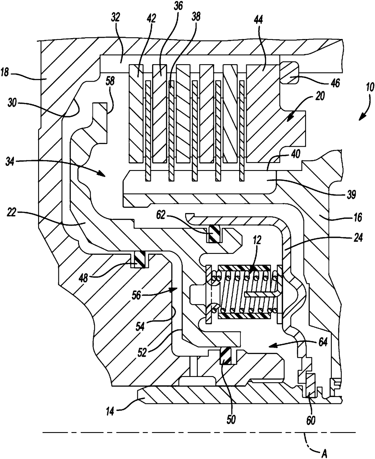
[0023] Referring to the drawings, wherein like reference numerals refer to like parts, figure 1 A cross-sectional view of the torque transmitting device 10 with a return spring pack assembly 12 for a transmission (not shown) of a motor vehicle is shown. The transmission may be a variable diameter pulley or sheave driven continuously variable transmission (CVT), a multi-speed planetary gear set automatic transmission or a manual transmission without departing from the scope of the present invention. The depicted exemplary torque transmitting device 10 is a hydraulically actuated piston multi-plate friction clutch. It should be understood that the torque transmitting device 10 may be a hydraulically actuated piston dog clutch, a cone clutch, a plate clutch or other torque transmitting device having a return spring pack assembly 12 without departing f...


PUM


Abstract

A torque transmitting device having a spring pack assembly, includes a first spring retainer ring abutting a hydraulically actuated piston, a second spring retainer ring abutting a piston housing, anda plurality of coiled springs biasing the first spring retainer ring apart from the second retainer ring, thereby urging the hydraulically actuated piston slideably apart from the fixed piston housing. A composite spring support ring is coaxially disposed between the first spring retainer ring and the second spring retainer ring. The spring support ring includes cylindrical walls defining cylindrical passageways configured to receive the coiled springs. Each of the cylindrical passageway includes include a diameter (d) that is sufficiently narrow such that the cylindrical wall completely surrounds the mid-portion of the coiled spring thus preventing the coiled spring from bending lengthwise, but sufficiently wide such that the coiled spring does not saw into the cylindrical walls.

Description

[0001] introduction [0002] The present invention relates to a torque transmitting device for an automatic transmission, and more particularly to a spring pack assembly for a torque transmitting device. Background technique [0003] Automatic transmissions for motor vehicles typically employ torque transmitting devices for selectively transmitting torque between transmission components. For example, hydraulically actuated friction clutches are used to hold and release elements of planetary gear sets in order to produce the various gear ratios required for operation of the motor vehicle. A hydraulically actuated clutch typically includes a hydraulic piston housing disposed within the hydraulic piston housing for selectively engaging a multi-plate clutch pack, a hydraulically actuated piston, and a return spring pack assembly for Actuates the hydraulically actuated piston to separate from the multi-plate clutch pack. [0004] A typical return spring pack assembly includes a p...

Claims


Application Information

Patent Timeline
Patent Type & Authority Applications(China)
IPC IPC(8): F16F3/08F16F3/087
CPCF16F3/08F16F3/087F16D25/0638F16D25/12F16F1/12F16D2127/02
Inventor G·W·德内斯楚克J·J·阿方索三世
Owner GM GLOBAL TECH OPERATIONS LLC
Learn More