Improved LED lamp

An LED lamp and an improved technology, applied in lighting and heating equipment, semiconductor devices of light-emitting elements, lighting devices, etc., can solve the problems of inconvenient installation and disassembly of the improved LED lamp, cumbersome installation operations, damage to indoor walls, etc. Increase the efficiency of installation and disassembly, avoid electric shock accidents, and ensure the safety and stability of electricity

Inactive Publication Date: 2018-06-29
卢振红
View PDF2 Cites 2 Cited by
  • Summary
  • Abstract
  • Description
  • Claims
  • Application Information

AI Technical Summary

Problems solved by technology

[0002] Improved LED lamps generally use LEDs as light sources, which are mostly installed on indoor walls. The existing improved LED lamps are widely used because of their high luminous efficiency, low power consumption, long life, easy control, energy saving and environmental protection. , but the existing improved LED lamps are fixed on the indoor wall by screws or bolts during the installation process. This installation method will not only cause damage to the indoor wall, but also the installation operation is more cumbersome, which is not convenient for the improved LED lamp. Quick installation and disassembly, and the existing improved LED lamps are installed after being powered on first and then fixed. This installation sequence is likely to cause electric shock accidents during installation, and there is a greater potential safety hazard

Method used


Image

  • Improved LED lamp
  • Improved LED lamp
  • Improved LED lamp

Examples


Embodiment Construction

[0020] The preferred embodiments of the present invention will be described in detail below in conjunction with the accompanying drawings, so that the advantages and features of the present invention can be more easily understood by those skilled in the art, so as to define the protection scope of the present invention more clearly.

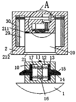
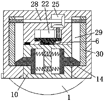
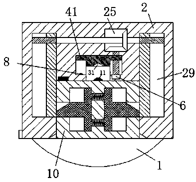
[0021] refer to Figure 1-4 As shown, an improved LED lamp of the present invention includes a housing 2 arranged in the wall and a lamp body 1 mated with the housing 2. An insertion cavity 20 is provided on the bottom surface of the housing 2. The insertion Locking sliding grooves 29 communicating with the insertion cavity 20 and extending upward are symmetrically arranged in the walls of the left and right ends of the cavity 20, and a power supply cavity 22 is arranged in the middle of the top wall of the insertion cavity 20, and in the walls of the left and right ends of the power supply cavity 22 A power slot 23 and a drive slot 24 communicat...


PUM


Abstract

The invention discloses an improved LED lamp. The lamp comprises a shell and a lamp body, wherein the shell is arranged in a wall, and the lamp body is connected with the shell in a cooperating mode;an insertion cavity is formed in the bottom end surface of the shell, and the left end wall and the right end wall of the insertion cavity are symmetrically provided with locking sliding grooves whichcommunicate with the insertion cavity and extend upwards; a power supply cavity is formed in the middle of the top end wall of the insertion cavity, and an electrifying groove and a driving groove which communicate with the power supply cavity are symmetrically arranged in the left end wall and the right end wall of the power supply cavity; and a gear containing groove is formed in the shell, andis located above the driving groove. According to the improved LED lamp, the lamp body is firmly locked, and is electrified safely and stably; when the lamp body is installed, the lamp body is electrified while the lamp body is locked; when the lamp body is disassembled, the lamp body is subjected to electricity disconnection, and meanwhile is unlocked; and the whole lamp is convenient and rapidto operate, stability of lamp body locking and power supply is improved, mounting and dismounting efficiency of the lamp body is greatly improved, electric shock accidents caused when the lamp body ismounted and dismounted are effectively avoided, and life safety of installing personnel is guaranteed.

Description

technical field [0001] The invention relates to the technical field of LEDs, in particular to an improved LED lamp. Background technique [0002] Improved LED lamps generally use LEDs as light sources, which are mostly installed on indoor walls. The existing improved LED lamps are widely used because of their high luminous efficiency, low power consumption, long life, easy control, energy saving and environmental protection. , but the existing improved LED lamps are fixed on the indoor wall by screws or bolts during the installation process. This installation method will not only cause damage to the indoor wall, but also the installation operation is more cumbersome, which is not convenient for the improved LED lamp. Quick installation and disassembly, and the existing improved LED lamps are installed after being powered on first and then fixed. Such an installation sequence is likely to cause electric shock accidents during installation by the installers, and there is a gre...

Claims


Application Information

Patent Timeline
Patent Type & Authority Applications(China)
IPC IPC(8): F21S8/00F21V19/00F21V21/002F21V23/06F21V25/00F21Y115/10
CPCF21S8/035F21V19/0025F21V21/002F21V23/06F21V25/00F21Y2115/10
Inventor 卢振红
Owner 卢振红
Why Eureka
Try Eureka