Design Method of Freeform Surface Imaging Optical System

A technology of imaging optics and design methods, applied in optics, optical components, optical radiation measurement, etc., can solve problems such as insufficient function, failure, limited initial structure, etc., to achieve the effect of reducing labor and high imaging quality

Active Publication Date: 2020-01-07
TSINGHUA UNIV +1
View PDF3 Cites 2 Cited by
  • Summary
  • Abstract
  • Description
  • Claims
  • Application Information

AI Technical Summary

Problems solved by technology

[0003] However, this design approach is not very smart or powerful enough
First, this design method is highly dependent on the initial structure, but the available initial structures are generally limited. If the structure and parameters of the initial structure are far from the design requirements, long-term optimization may be required
Moreover, for some imaging optical systems with advanced indicators and special structures, it is likely that it is impossible to find a suitable initial structure.
In this way, the designer is likely to spend a lot of time optimizing, or even fail

Method used


Image

  • Design Method of Freeform Surface Imaging Optical System
  • Design Method of Freeform Surface Imaging Optical System
  • Design Method of Freeform Surface Imaging Optical System

Examples


Embodiment Construction

[0020] The technical solution of the present invention will be further described in detail below according to the drawings in the description and in combination with specific embodiments.

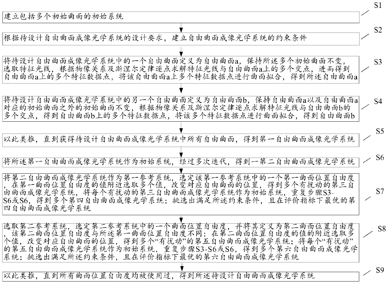
[0021] see figure 1 , the present invention provides a kind of design method of free-form surface imaging optical system, it comprises the following steps:

[0022] Step S1, establishing an initial system, the initial system includes a plurality of initial curved surfaces, and one initial curved surface in the initial system corresponds to a free-form surface in the free-form surface imaging optical system to be designed;

[0023] Step S2, according to the design requirements of the free-form surface imaging optical system to be designed, the constraint conditions of the free-form surface imaging optical system are established;

[0024] Step S3, define a free-form surface in the free-form surface imaging optical system to be designed as a free-form surface a, keep the multiple initial surf...


PUM


Abstract

The invention relates to a design method of a free-form surface imaging optical system, comprising: establishing an initial system; selecting characteristic light rays, solving the characteristic data points on the free-form surface a, and fitting to obtain the free-form surface a; and so on, obtaining the first free-form surface imaging optical system system; the first free-form surface imaging optical system is used as the initial system, and the second free-form surface imaging optical system is obtained through multiple iterations; the second free-form surface imaging optical system is used as a reference system, and a curved surface position degree of freedom is selected, and at the curved surface position Select multiple values ​​near the value of the degree of freedom, change the position of the corresponding curved surface, and obtain multiple third free-form surface imaging optical systems; use each third free-form surface imaging optical system as the initial system, repeat the iterative steps, and obtain multiple fourth Freeform surface imaging optical system; select the fourth freeform surface imaging optical system that satisfies the constraints and is optimal under the evaluation index; and so on, until all surface position degrees of freedom have been used.

Description

technical field [0001] The invention relates to the field of optical design, in particular to an automatic design method for a free-form surface imaging optical system. Background technique [0002] In the existing design methods of imaging optical systems, the design process is generally to first find a good initial structure, and then perform computer-aided optimization. [0003] However, this design approach is not very smart or powerful enough. First, this design method is highly dependent on the initial structure, but the available initial structures are generally limited. If the structure and parameters of the initial structure are far from the design requirements, long-term optimization may be required. Moreover, for some imaging optical systems with advanced indicators and special structures, it may not be possible to find a suitable initial structure. In this way, the designer is likely to spend a lot of time optimizing, or even fail. Second, the optimization pro...

Claims


Application Information

Patent Timeline
Patent Type & Authority Patents(China)
IPC IPC(8): G02B27/00
CPCG02B27/0012G02B3/02G01J3/0289G01J2003/283G01J3/2823
Inventor 朱钧杨通吴晓飞金国藩范守善
Owner TSINGHUA UNIV
Why Eureka
Try Eureka