Flexible display panel, preparation method and display device thereof
A flexible display and panel technology, applied in the direction of identification devices, instruments, organic semiconductor devices, etc., can solve problems that affect the normal display of flexible display products, poor signal transmission, breakage, etc., to achieve narrow borders or even full screen without borders, and realize the design effect, the effect of avoiding breakage
- Summary
- Abstract
- Description
- Claims
- Application Information
AI Technical Summary
Problems solved by technology
Method used
Image

Examples
Embodiment 1
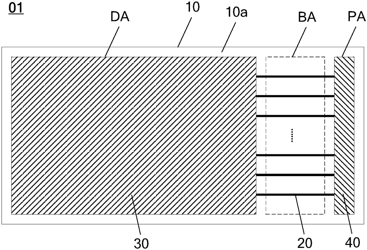
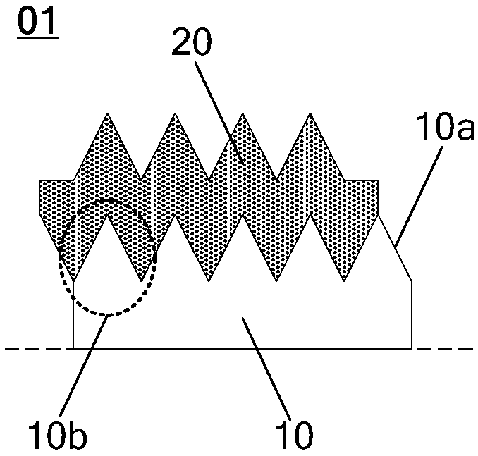
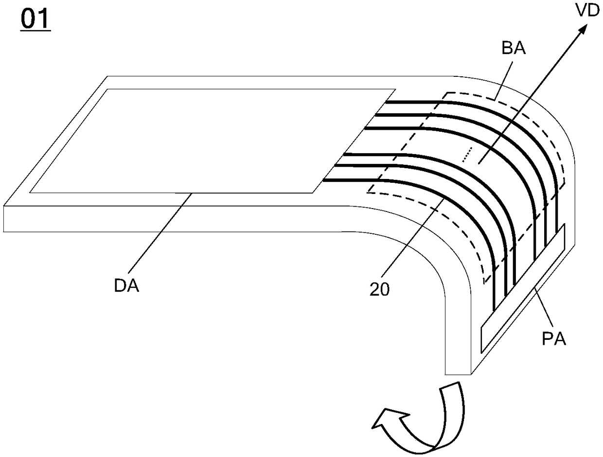
[0043] Such as figure 1 As shown, Embodiment 1 of the present invention provides a flexible display panel 01, the flexible display panel 01 includes: a flexible base substrate 10; the flexible base substrate 10 includes: a first surface 10a; the first surface 10a is divided into curved Bending area (Bending area, figure 1 and the following drawings are marked as BA); if figure 2 As shown, the first surface 10a has a plurality of protrusions 10b in the bending area; the signal lead-out line 20 is located above the first surface 10a and passes through the bending area.
[0044] It should be noted that the above figure 2 It only shows the situation that the signal lead-out line 20 is located above the first surface 10a of the flexible substrate 10, and the signal lead-out line 20 is in direct contact with the first surface 10a in the bending area, which is not described in Embodiment 1 of the present invention. It is limited, as long as the signal lead-out line 20 is located...
Embodiment 2
[0064] On the basis of the above, Embodiment 2 of the present invention further provides a method for preparing the above-mentioned flexible display panel, the method comprising the following steps:
[0065] Step 1, providing a flexible substrate, the flexible substrate includes: a first surface; the first surface is divided into a bending area;
[0066] Step 2, patterning the part of the first surface located in the bending area to form a plurality of protrusions in the bending area;
[0067] Step 3, forming a metal lead-out line located above the first surface and passing through the bending area.
[0068] Here, the step of patterning the part of the first surface of the flexible substrate located in the bending area to form a plurality of protrusions in the bending area can be exemplified by using a mask with a certain pattern, The part of the first surface located in the bending area is etched, and by etching away a part of the area, the remaining part of the first surfac...
Embodiment 3
[0074] The following solution provided by Embodiment 3 aims to completely remove the insulating layer between the metal lead-out wire and the flexible substrate in the bending area, so that the signal lead-out wire 20 is directly in contact with the protrusion on the first surface in the bending area. Contact each other to form a structure one after another. The specific structure is as follows:
[0075] Such as Figure 5 As shown, the signal lead-out line 20 includes: a second surface 20a away from the flexible substrate 10; wherein, in the bending area BA, the second surface 20a covers the plurality of protrusions 10b and is correspondingly uneven (such as Figure 5 magnified part of the dotted box).
[0076] Here, along the vertical direction of the flexible substrate board surface, the shape of the protrusion 10b is not limited to the above-mentioned Figure 5The triangle shown in , that is, the first surface of the flexible substrate 10 is in a zigzag shape in the bend...
PUM
 Abstract
Description
Claims
Application Information
 - R&D
- Intellectual Property
- Life Sciences
- Materials
- Tech Scout
- Unparalleled Data Quality
- Higher Quality Content
- 60% Fewer Hallucinations
Browse by: Latest US Patents, China's latest patents, Technical Efficacy Thesaurus, Application Domain, Technology Topic, Popular Technical Reports.
© 2025 PatSnap. All rights reserved.Legal|Privacy policy|Modern Slavery Act Transparency Statement|Sitemap|About US| Contact US: help@patsnap.com