Magnetic motor brake

A magnetic brake and magnetic brake seat technology, applied in the field of motor magnetic brakes, can solve the problems of narrow application area of ​​a single product, inconvenient product maintenance, low product cost performance, etc., and achieve the effects of low cost, easy maintenance, and simple maintenance process.

Pending Publication Date: 2018-06-29
NANJING KANGNI SMART TECH CO LTD
View PDF0 Cites 1 Cited by
  • Summary
  • Abstract
  • Description
  • Claims
  • Application Information

AI Technical Summary

Problems solved by technology

[0002] Most of the existing motor magnetic brakes use a combination of stators, moving plates, friction plates, magnetic brake seats and corresponding screws, spacers, springs, etc. The structure is complex, the application area of ​​a single product is narrow, and the cost is high.
At the same time, the maintenance of the product is inconvenient and requires professionals to operate, the maintenance cost is high, and the product cost performance is low

Method used


Image

  • Magnetic motor brake
  • Magnetic motor brake

Examples


Embodiment 1

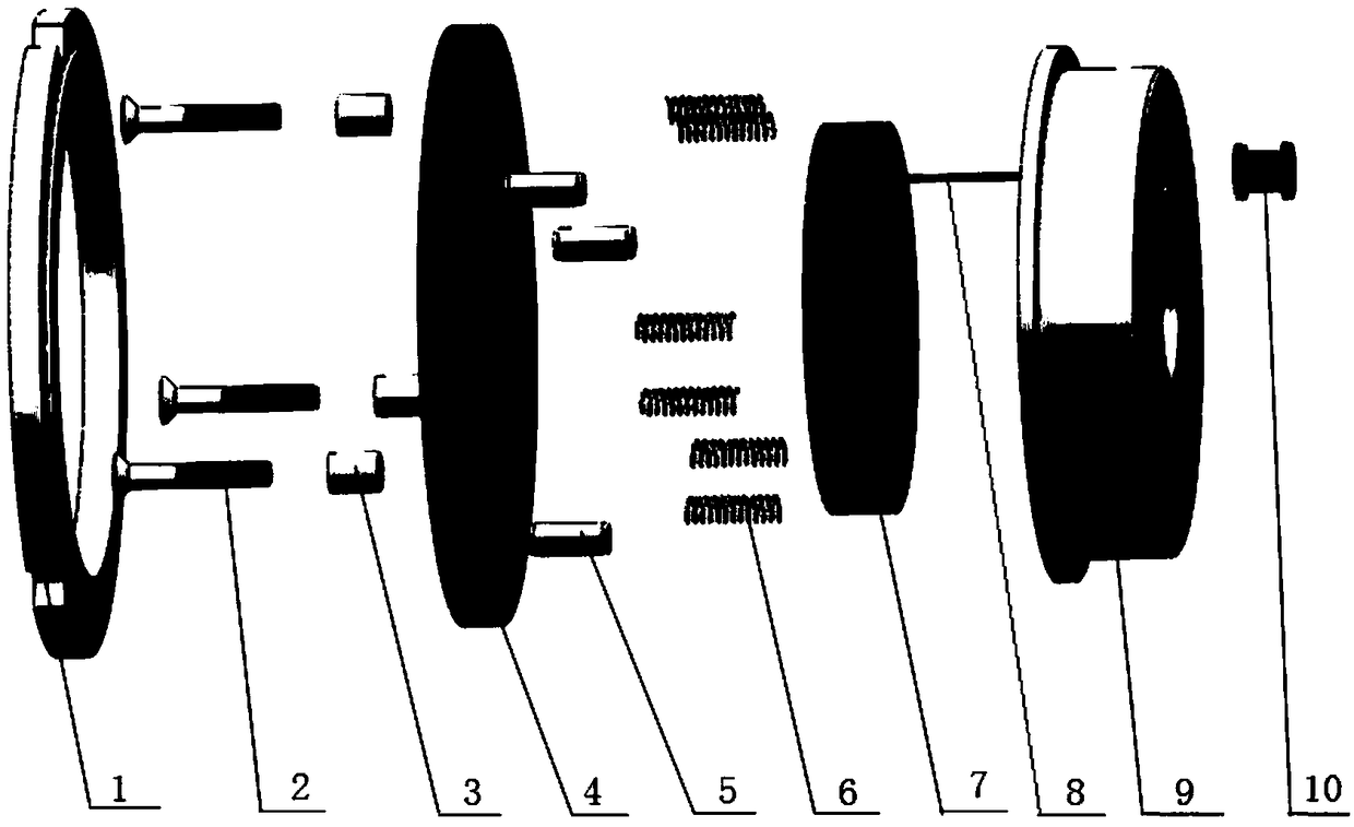
[0020] Embodiment 1: A kind of motor magnetic brake, such as figure 1 As shown, it includes a magnetic brake seat 9, a magnetic coil 7, a return spring 6, a moving plate / fixed plate combination plate 4, a screw 2, a spacer 3, a pin 5 and a friction ring 1.

[0021] The magnetic brake seat 9 is fixed with the motor shaft through the keyway of the inner hole and the key pin, so as to keep the circumferential positioning of the magnetic brake seat 9; The units contact to form the axial positioning of the magnetic brake seat 9. The inside of the magnetic brake seat 9 is provided with an annular groove, and the inner surface and outer edge of the magnetic brake seat 9 are evenly provided with positioning holes 12, and the inner surface of the magnetic brake seat 9 is evenly provided with threaded holes 13 at the middle position. An outgoing line protection ring 10 is provided on the outer surface of the magnetic brake seat 9 .

[0022] The positioning hole 12 is correspondingly p...

Embodiment 2

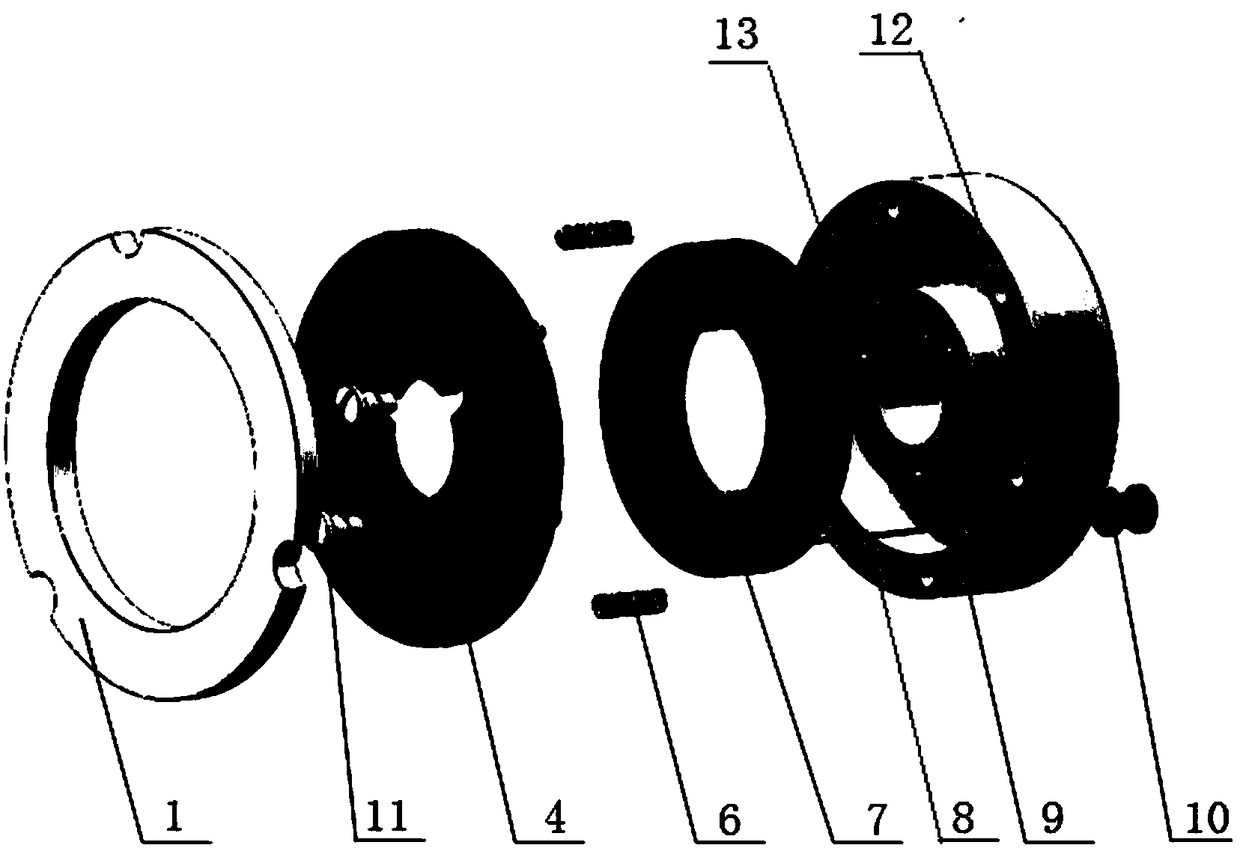
[0026] Embodiment 2: a kind of motor magnetic brake, such as figure 2 As shown, it includes a magnetic brake seat 9, a magnetic coil 7, a return spring 6, a moving plate / fixed plate combination plate 4, a shaft screw 11 and a friction ring 1.

[0027] The magnetic brake seat 9 is fixed with the motor shaft through the keyway of the inner hole and the key pin, so as to keep the circumferential positioning of the magnetic brake seat 9; The units contact to form the axial positioning of the magnetic brake seat 9. The inside of the magnetic brake seat 9 is provided with an annular groove, and the inner surface and outer edge of the magnetic brake seat 9 are evenly provided with positioning holes 12, and the inner surface of the magnetic brake seat 9 is evenly provided with threaded holes 13 at the middle position. An outgoing line protection ring 10 is provided on the outer surface of the magnetic brake seat 9 .

[0028] The positioning hole 12 is correspondingly provided with ...


PUM


Abstract

The invention discloses a magnetic motor brake. The magnetic motor brake comprises a magnetic brake seat, a magnetic coil, reset springs, a rotor/stator combined plate and a friction ring and is characterized in that an annular groove is arranged inside the magnetic brake seat, the outer edge of the inner side of the magnetic brake seat is evenly provided with positioning holes, and the middle ofthe inner side of the magnetic brake seat is evenly provided with threaded holes; the magnetic coil is arranged in the annular groove of the inner cavity of the magnetic brake seat and connected witha switch; the magnetic coils are correspondingly arranged in the positioning holes; the rotor/stator combined plate is coordinated with the threaded holes in the magnetic brake seat through fastenersand connected with the magnetic brake seat to guarantee circumferential fixing and axial movement of the rotor/stator combined plate; the friction ring is arranged on the outer side of the rotor/stator combined plate and connected with the end cover of a motor. The magnetic motor brake is simple and optimized in overall structure, easy to assemble, convenient to maintain, wide in application rangeand suitable for being widely produced and used.

Description

technical field [0001] The invention relates to a brake for a motor, in particular to a magnetic brake for a motor. Background technique [0002] Most of the existing motor magnetic brakes use a combination of stator, moving plate, friction plate, magnetic brake seat and corresponding screws, spacers, springs, etc., which has a complex structure, narrow application range of a single product, and high cost. At the same time, the maintenance of the product is inconvenient, requires professional personnel to operate, the maintenance cost is high, and the cost performance of the product is relatively low. Contents of the invention [0003] Object of the invention: The object of the invention is to provide a motor magnetic brake for the deficiencies of the prior art. The present invention has a simple and optimized overall structure, is easy to assemble and maintain, has a wide range of applications, and is suitable for extensive production and application. [0004] Technical...

Claims


Application Information

Patent Timeline
Patent Type & Authority Applications(China)
IPC IPC(8): H02K7/102
CPCH02K7/1025
Inventor 唐达联金辉
Owner NANJING KANGNI SMART TECH CO LTD
Why Eureka
Try Eureka