
Novel interface structure

An interface structure, a new type of technology, applied in the layout combined with the fuel supply of the internal combustion engine, the sealing of the engine, the engine components, etc., can solve the problems of high evaporative emission limit, uneven material wall thickness, high leakage risk, and achieve the wall thickness Uniform distribution, reducing the probability of exudation, and good sealing performance

Pending Publication Date: 2018-07-03
STANT AUTOMOTIVE SYST SUZHOU
View PDF12 Cites 1 Cited by
  • Summary
  • Abstract
  • Description
  • Claims
  • Application Information

AI Technical Summary

Problems solved by technology

[0004] In the existing interface structure, the lower annular surface of the upper cover is fastened and connected to the welding ring through multiple sets of vertical concave-convex grooves, and then connected to the corresponding body structure through the welding ring. The corresponding concave-convex groove structure makes the joint surface of the two materials longer, and the setting of the concave-convex groove makes the wall thickness of the material uneven, and there is a risk of leakage at the interface, especially after the product has passed various oil soaking and reliability tests. Higher risk of leaks resulting in higher evaporative emission limits

Method used


Image

  • Novel interface structure
  • Novel interface structure

Examples


Embodiment Construction

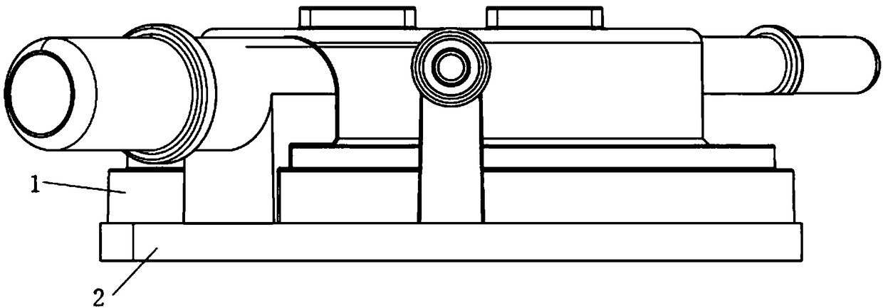
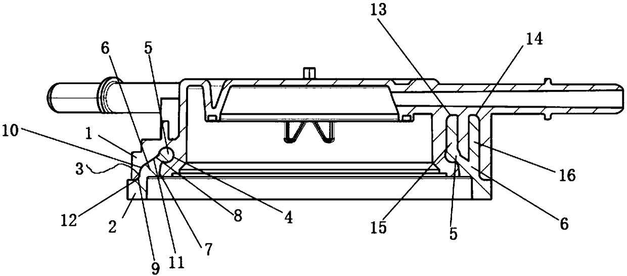
[0020] A new interface structure, see figure 1 , figure 2 : It includes a loam cake 1 and a welding ring 2. The lower annular surface of the loam cake 1 is provided with a concave annular groove 3. The longitudinal section of the annular groove 3 includes transition edges on both sides and an undercut cavity 4 on the top. The welding ring 2 corresponds to At the corresponding position of the annular groove 2, there is an upwardly convex undercut component. The longitudinal section of the undercut component includes the top undercut 5 and the lower transition connector 6. In the connected state, the undercut 5 enters into the Inside the top undercut cavity 4 , the two side edges of the transition connector 6 are arranged close to the transition edges of the corresponding sides, and the undercut 5 is arranged close to the inner wall of the top undercut cavity 4 .

[0021] The transition edges on both sides are the inner transition edge 7 and the outer transition edge 8 respect...


PUM


Abstract

The invention provides a novel interface structure which allows a lower annular surface of an upper cover and a welding ring to be connected in an inverted manner, so that a bonding path is shortenedand the sealing performance at an interface joint is good, so as to reduce the probability of carbon-hydrogen molecules leaking from the interface joint. The novel interface structure comprises the upper cover and the welding ring, wherein the lower annular surface of the upper cover is provided with an inwardly-concave annular groove; the longitudinal section of the annular groove comprises transition edges on the two sides and a top inverted cavity; the welding ring is provided with an upwardly-convex inverted assembly at the position corresponding to the annular groove; the longitudinal section of the inverted assembly comprises an inverted part at the top part and a transition connector at the lower part; the inverted part enters into the top inverted cavity along the transition edgeson the two sides under the connection state; the two edges of the transition connector cling to the transition edges on the corresponding sides; and the inverted part clings to the inner wall of the top inverted cavity.

Description

technical field [0001] The invention relates to the technical field of fuel system interfaces, in particular to a novel interface structure. Background technique [0002] As the national environmental protection requirements become more and more stringent, especially the release of China's sixth-stage "Light Vehicle Pollutant Emission Limits and Measurement Methods" draft regulations that have a greater impact on the entire automotive industry, it is also known in the industry as " "National Six Regulations", all models currently under development must meet the requirements of the draft, especially the type IV test, which puts forward higher requirements for the evaporative emission limits of the whole vehicle, especially the fuel system components . [0003] How the fuel system meets the more stringent evaporative emission limits not only needs to consider the layout design of the entire fuel system, but also poses new challenges to the structure and material usage of each...

Claims


Application Information

Patent Timeline
Patent Type & Authority Applications(China)
IPC IPC(8): B60K15/00F16J15/04
CPCF16J15/04B60K15/00
Inventor 李春
Owner STANT AUTOMOTIVE SYST SUZHOU
Learn More