
Method for Improving Stability of Friction Wheel Separating Cloth and Cloth Separating Device

A technology of separation device and friction wheel, which is applied in the direction of pile separation, thin material processing, object separation, etc., can solve the problems of reduced success rate, achieve the effect of improving stability, increasing contact area, and ensuring success rate

Active Publication Date: 2020-06-23
JACK SEWING MASCH CO LTD
View PDF5 Cites 0 Cited by
  • Summary
  • Abstract
  • Description
  • Claims
  • Application Information

AI Technical Summary

Problems solved by technology

Due to the soft physical properties of the fabric, the contact surface with the friction wheel is an arc surface, and as the equivalent stiffness of the bottom increases, this contact surface will continue to decrease, resulting in a lower separation success rate

Method used


Image

  • Method for Improving Stability of Friction Wheel Separating Cloth and Cloth Separating Device
  • Method for Improving Stability of Friction Wheel Separating Cloth and Cloth Separating Device

Examples


Embodiment 1

[0029] Embodiment 1 provides an embodiment of the method for improving the stability of the friction wheel separating cloth according to the present invention.

[0030] The method of improving the stability of the friction wheel to separate the cloth in the first embodiment is as follows: set a friction member made of flexible material or elastic material under the friction wheel, and place the cloth to be separated on the friction member. When the outer surface of the friction wheel is in contact with the uppermost layer of cloth in a stack of cloth to be separated, the rotation of the friction wheel drives this layer of cloth to slide forward and separate from the stack of cloth to be separated.

[0031] Since the friction parts are made of flexible materials or elastic materials, the friction parts can be deformed under the pressure of the friction wheel when the cloth is separated, so the equivalent stiffness of the part below the uppermost cloth of the cloth to be separate...

Embodiment 2

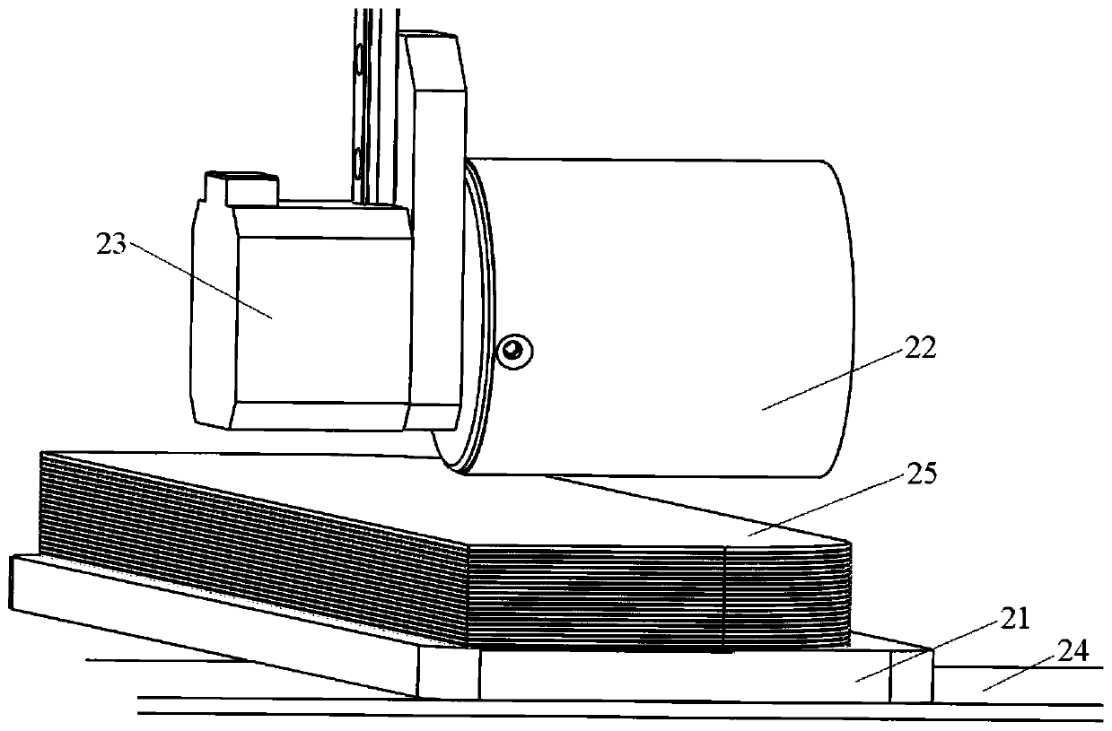
[0037] Such as figure 2 As shown, Embodiment 2 provides an embodiment of the cloth separating device of the present invention. The material separating device of the second embodiment is used to realize the method for improving the stability of the friction wheel separating the material described in the first embodiment.

[0038] The cloth separating device of the second embodiment includes: a friction component 21 , a friction wheel 22 and a driving component 23 . The friction member 21 is used to place the cloth 25 to be separated. The friction member 21 of the second embodiment is made of flexible material or elastic material, and the friction member 21 can move up and down. The friction wheel 22 is arranged above the friction member 21 , and the axis of the friction wheel 22 is parallel to the upper surface of the cloth to be separated 25 placed on the friction member 21 . The driving part 23 is connected with the friction wheel 22, and the driving part 23 drives the fri...


PUM


Abstract

The invention relates to the technical field of cloth separation, in particular to a method for improving the stability of cloth separation by a friction wheel. The method comprises the steps that a friction component made of flexible materials or elastic materials is arranged below the friction wheel, and cloth to be separated is arranged on the friction component. The invention further relates to a cloth separating device comprising the friction component used for holding the cloth to be separated, the friction wheel arranged above the friction component, and a driving component connected tothe friction wheel; the friction component is made of the flexible materials or the elastic materials, and can be moved up and down; the axis of the friction wheel is parallel with the upper surfaceof the cloth to be separated; and the friction wheel is driven by the driving component to rotate around the axis. The friction component can be deformed under the pressure effect of the friction wheel, so that the contact area between the topmost cloth of the cloth to be separated and the friction wheel is increased; and especially when only last few layers of cloth remain, the good cambered surface contact between the topmost cloth and the friction wheel can also be ensured so that the success rate of the cloth separation is guaranteed.

Description

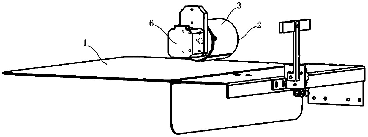
technical field [0001] The invention relates to the technical field of material separation, in particular to a method for improving the stability of material separation by a friction wheel and a material separation device. Background technique [0002] In the prior art, the invention patent application whose publication number is CN105923427A records a kind of cloth automatic separation and taking device, such as figure 1 As shown, the device includes a lifting plate 1 that can move up and down. Cloth is placed on the upper surface of the lifting plate 1. A roller 2 is arranged above the lifting plate 1. A friction layer 3 is attached to the circumferential surface of the roller 2. The friction layer 3 And roller 2 constitute friction wheel. The axis of the roller 2 is parallel to the upper surface of the lifting plate 1, and the roller 2 rotates around the axis under the drive of the motor 6. When the lifting plate 1 with a stack of fabrics is placed on it, it moves upward...

Claims


Application Information

Patent Timeline
Patent Type & Authority Patents(China)
IPC IPC(8): B65H3/06
CPCB65H3/06B65H2405/1118
Inventor 丁世潮李帅鹏
Owner JACK SEWING MASCH CO LTD
Learn More