
Reserved hole forming composite pattern plate of shear wall used for outrigger, shear wall, reserved hole plugging block and method thereof

A technology of reserving openings and combining formwork, which is applied in the field preparation of formwork/formwork/work frame, building components, construction, etc. It can solve the problems of falling objects from high altitude and troublesome installation of external formwork, so as to prevent falling objects from high altitude , Ease of use

Pending Publication Date: 2018-07-03
DONGHUA CONSTR COMPANY LTD OF YANKUANG GRP
View PDF6 Cites 3 Cited by
  • Summary
  • Abstract
  • Description
  • Claims
  • Application Information

AI Technical Summary

Problems solved by technology

[0002] The cantilevered scaffolding of the high-rise shear wall structure generally adopts the cantilevered I-beam as the supporting foundation of the scaffold. When the cantilevered layer shear wall is constructed, the cantilevered I-beam hole should be reserved. After the scaffold and the I-beam are removed, The opening needs to be re-formed and poured concrete, and the installation of the outer formwork is very troublesome, which can easily lead to falling objects

Method used


Image

  • Reserved hole forming composite pattern plate of shear wall used for outrigger, shear wall, reserved hole plugging block and method thereof
  • Reserved hole forming composite pattern plate of shear wall used for outrigger, shear wall, reserved hole plugging block and method thereof
  • Reserved hole forming composite pattern plate of shear wall used for outrigger, shear wall, reserved hole plugging block and method thereof

Examples


Embodiment approach 1

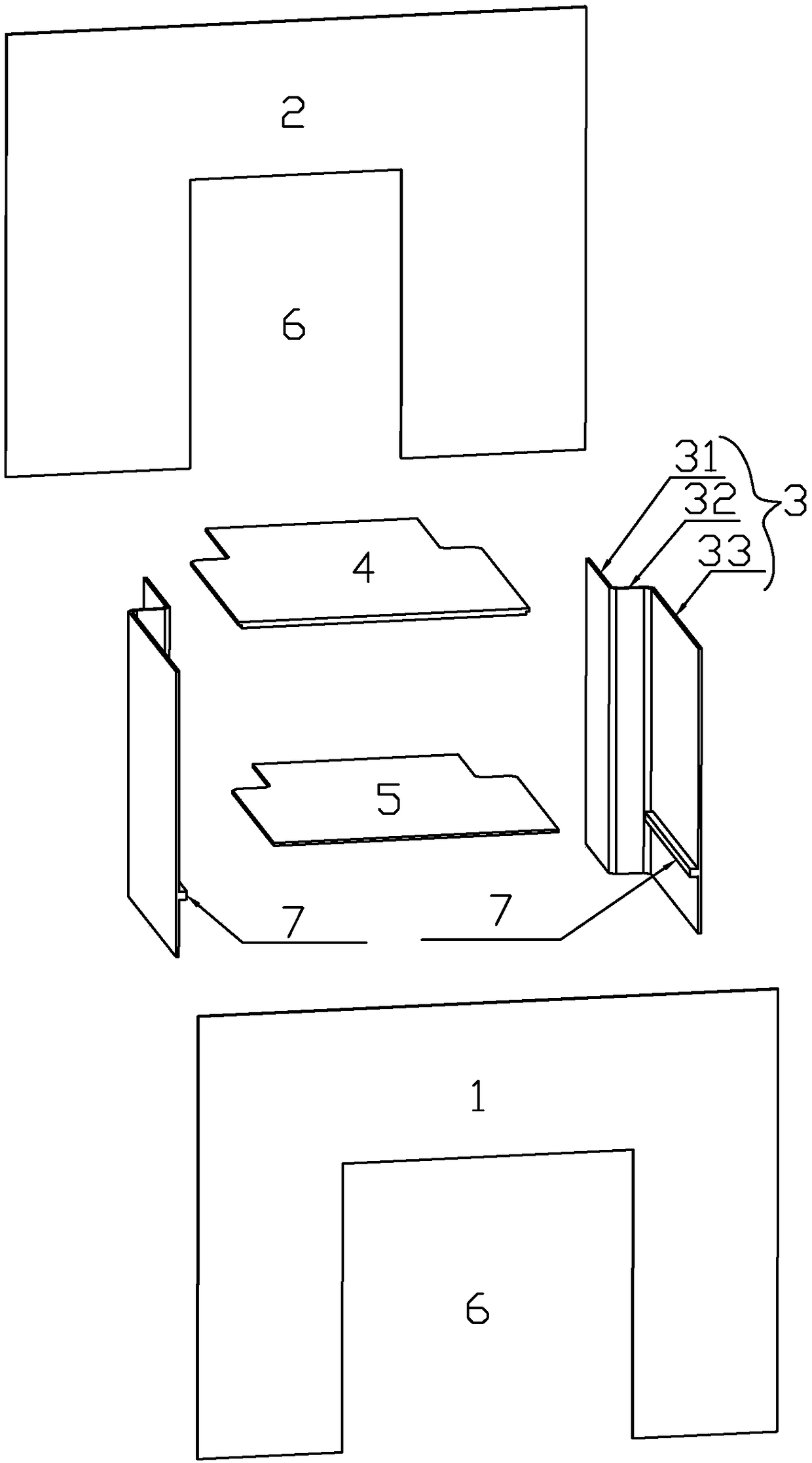
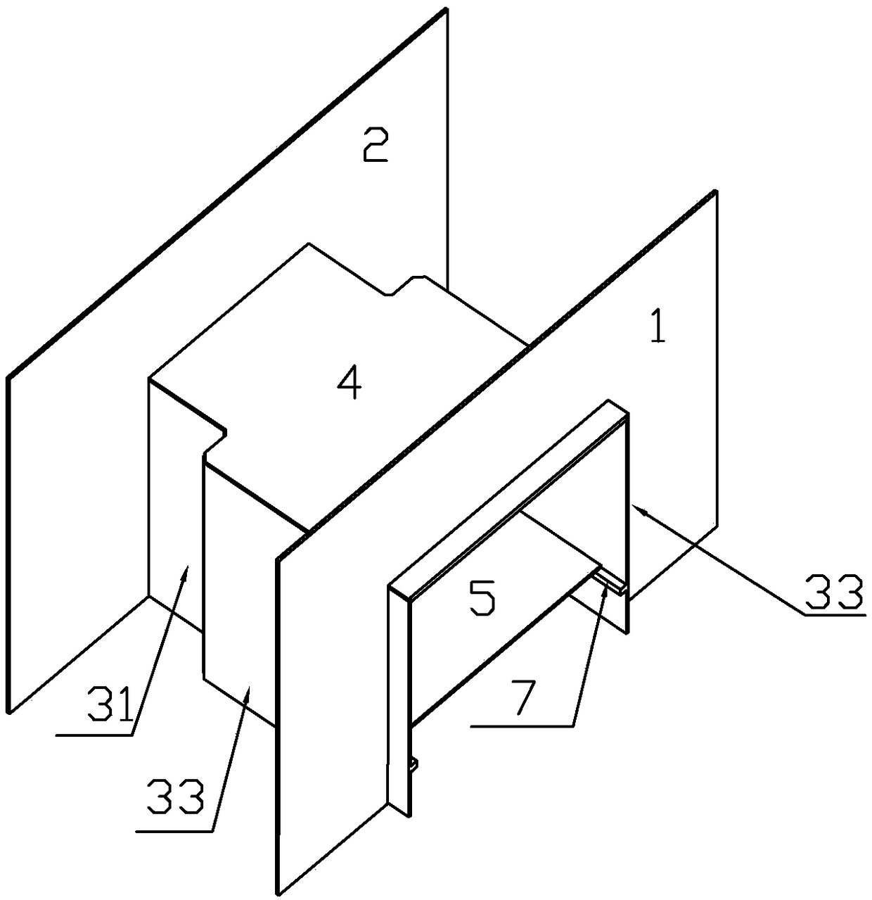
[0038] Implementation mode one: if Figure 1-2 As shown, the cantilever uses a shear wall reserved opening to form a combined formwork, including an inner formwork 1, an outer formwork 2, two vertical side panels 3, a roof 4 and a support plate 5, and the inner formwork 1 and the outer formwork 2 are provided with Opposed to the square notch 6, the upper surfaces of the front and rear ends of the top plate 4 are respectively attached to the upper edges of the two square notches 6, and the left and right sides of the top plate 4 are respectively pressed on the upper edges of the two vertical side plates 3, and the two vertical The side plates 3 abut against the side walls of the square notch 6 at the front and rear respectively, the support plate 5 is parallel to the top plate 4 , and its left and right ends respectively abut against the inner surfaces of the two vertical side plates 3 . The horizontal width of the square notch 6 of the inner template 1 is greater than the hori...


PUM


Abstract

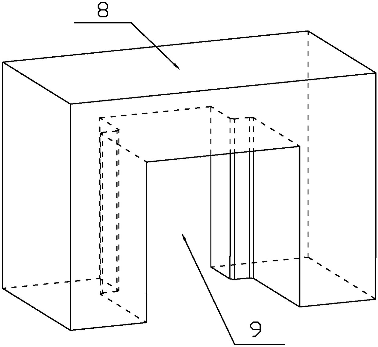
The invention relates to a reserved hole forming composite pattern plate of a shear wall used for an outrigger, a shear wall, a reserved hole plugging block and a method thereof. An existing reservedhole plugging technology for the shear wall used for the outrigger easily results in falling of an object from high altitude. The reserved hole forming composite pattern plate of the shear wall used for the outrigger comprises an inner pattern plate, an outer pattern plate, two vertical side plates, a top plate and a supporting plate, opposite square gaps are formed in the inner pattern plate andthe outer pattern plate, horizontal width of the square gap of the inner pattern plate is larger than that of the square gap of the outer pattern plate, each vertical side plate is composed of a frontplate, an intermediate plate and a rear plate, each front plate and the corresponding rear plate are parallel to each other, the outer side of each middle plate is vertically intersected with the front edge of the corresponding rear plate, the inner side of each middle plate is vertically intersected with the rear edge of the front plate, and projection of the top plate on the horizontal plane isshaped like a Chinese character 'TU'. The invention also relates to a corresponding shear wall, a reserved hole plugging block and a method thereof. The reserved hole forming composite pattern plateprovided by the invention has the advantages of being easy to use and completely eradicating falling of the object from high altitude and is applicable to being used by cantilevered scaffolds of various buildings.

Description

technical field [0001] The invention relates to a combined template for forming a reserved opening of a shear wall for cantilever beams, a shear wall, a blocking block for a reserved opening and a method thereof. Background technique [0002] The cantilevered scaffolding of the high-rise shear wall structure generally adopts the cantilevered I-beam as the supporting foundation of the scaffold. When the cantilevered layer shear wall is constructed, the cantilevered I-beam hole should be reserved. After the scaffold and the I-beam are removed, The opening needs to be re-formed to pour concrete, and the installation of the outer formwork is very troublesome, which can easily lead to falling objects. Contents of the invention [0003] The technical problem to be solved by the present invention is how to overcome the above-mentioned defects of the prior art, and provide a combination formwork for forming a shear wall with a reserved opening for cantilever beams, a shear wall, a...

Claims


Application Information

Patent Timeline
Patent Type & Authority Applications(China)
IPC IPC(8): E04G11/06E04G15/06
CPCE04G11/06E04G15/06
Inventor 韩鹏孔繁聪唐群
Owner DONGHUA CONSTR COMPANY LTD OF YANKUANG GRP
Learn More