
Spiral linear motor

A linear motor and screw technology, applied in electrical components, electromechanical devices, electric components, etc., can solve the problems of electromagnetic thrust, efficiency, low power factor, unbalanced winding current, large magnetizing current, etc. Enhanced electromagnetic thrust, easy to process and manufacture

Inactive Publication Date: 2018-07-03
徐建宁
View PDF0 Cites 3 Cited by
  • Summary
  • Abstract
  • Description
  • Claims
  • Application Information

AI Technical Summary

Problems solved by technology

[0002] The iron core length of the conventional induction linear motor is relatively short. Although it is connected to a symmetrical three-phase alternating current, the winding current is unbalanced; due to the edge effect, a large magnetizing current is required; therefore, the electromagnetic thrust and efficiency generated by the linear motor , power factor, etc. are lower than rotating motors with the same capacity

Method used


Image

  • Spiral linear motor
  • Spiral linear motor

Examples


Embodiment Construction

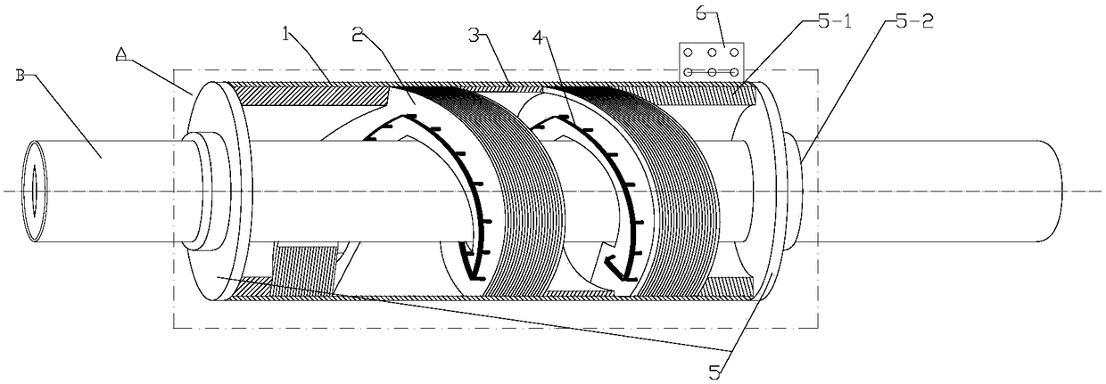
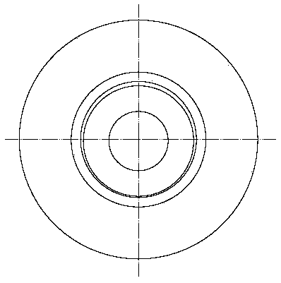
[0020] Such as figure 1 , 2 Shown: a helical linear motor, including: a stator A, a mover B set with the stator A; the stator A is composed of a shell 1, a spiral iron core 2 and a spiral spacer 3 set in the shell 1, The windings 4 distributed in several notches of the spiral core 2 are composed of two end caps 5 connected to the two ends of the housing 1; the characteristic is that the spiral core 2 is composed of inner circles or outer circles of several annular silicon steel sheets. Punch evenly distributed notches, and break a gap at the same position of several annular silicon steel sheets; pull several annular silicon steel sheets axially from the gap to form spiral silicon steel sheets with equal pitch, and several spiral silicon steel sheets After the two sides are coated with an insulating layer, they are stacked together in the axial direction, and the notches of several spiral silicon steel sheets are aligned, and the axes of the notches must be perpendicular to th...


PUM


Abstract

The invention discloses a spiral linear motor. A stator core is made into a single-turn or multi-turn spiral iron core with an equal screw pitch, and the moving pitch of a mover depends on the spiralspacing of the stator spiral iron core. The spiral iron core is divided into two types including an inner notch type and an outer notch type. A three-phase winding is embedded in the notch of the spiral iron core. The mover for outputting electromagnetic force is a cylindrical metal electric conductor, and the mover is sleeved in the stator and can rotate and slide. When the stator is connected tothree-phase alternating current, a spiral magnetic field which is consistent with a spiral angle of the spiral iron core is generated in the spiral iron core, the surface of the mover corresponding to the spiral magnetic field induces a spiral eddy current magnetic field whose direction is consistent with a spiral magnetic field direction, and the spiral eddy current magnetic field of the mover and the spiral magnetic field of the stator interact to allow the mover to do helical motion with the equal screw pitch in a speed lower than the rotation speed of the stator spiral magnetic field. Thespiral linear motor is used as an induction motor capable of outputting torque and outputting axial force and is suitable for an occasion with the need of long-distance linear propulsion.

Description

technical field [0001] The invention relates to a helical linear motor, in particular to the field of induction linear motors. Background technique [0002] The iron core length of the conventional induction linear motor is relatively short. Although it is connected to a symmetrical three-phase alternating current, the winding current is unbalanced; due to the edge effect, a large magnetizing current is required; therefore, the electromagnetic thrust and efficiency generated by the linear motor , power factor, etc. are lower than rotating motors with the same capacity. Contents of the invention [0003] The invention provides a helical linear motor, which is a helical iron core with a single or multiple turns and an equal pitch, and the moving pitch of the mover depends on the size of the helical interval of the stator helical iron core; the helical iron core The larger the distance between the spirals of the core, the faster the linear motion speed of the mover, otherwis...

Claims


Application Information

Patent Timeline
IPC IPC(8): H02K41/025
CPCH02K41/025
Inventor 徐建宁
Owner 徐建宁
Learn More