Soybean milk machine

A soymilk machine and cup body technology, applied in the field of soymilk machine, can solve the problems of strong sense of heaviness, unattractive appearance, heavy overall weight of the machine head, etc., achieve reduction in the thickness and weight of the machine head, facilitate operation and observation, and improve portability Effect

Inactive Publication Date: 2018-07-06
JOYOUNG CO LTD
View PDF5 Cites 2 Cited by
  • Summary
  • Abstract
  • Description
  • Claims
  • Application Information

AI Technical Summary

Problems solved by technology

[0002] The existing soybean milk machine includes a machine head and a cup body, and the top surface of the machine head is an operation / display interface, and a control device for controlling the operation / display interface is arranged in the machine head, and at the same time, electrical components such as motors are also installed in the machine head , so the space in the machine head needs to be set larger to take advantage of the installation of these electrical components and effective heat dissipation, which results in a thicker machine head and a heavier overall weight of the machine head, not only the appearance is not beautiful, but also For the elderly and children, the heaviness of lifting the nose is stronger
Secondly, when consumers use the soymilk machine, they need to get close to the top of the soymilk machine to be able to observe the operation function and interface display menu of the soymilk machine normally, which is not conducive to long-distance observation by users
Finally, the display and operation interface area on the top of the general soymilk machine head is limited, resulting in more functions of the soymilk machine, the display of button patterns and / or fonts will become smaller, and the user's experience will be further reduced

Method used


Image

  • Soybean milk machine
  • Soybean milk machine
  • Soybean milk machine

Examples


Embodiment 1

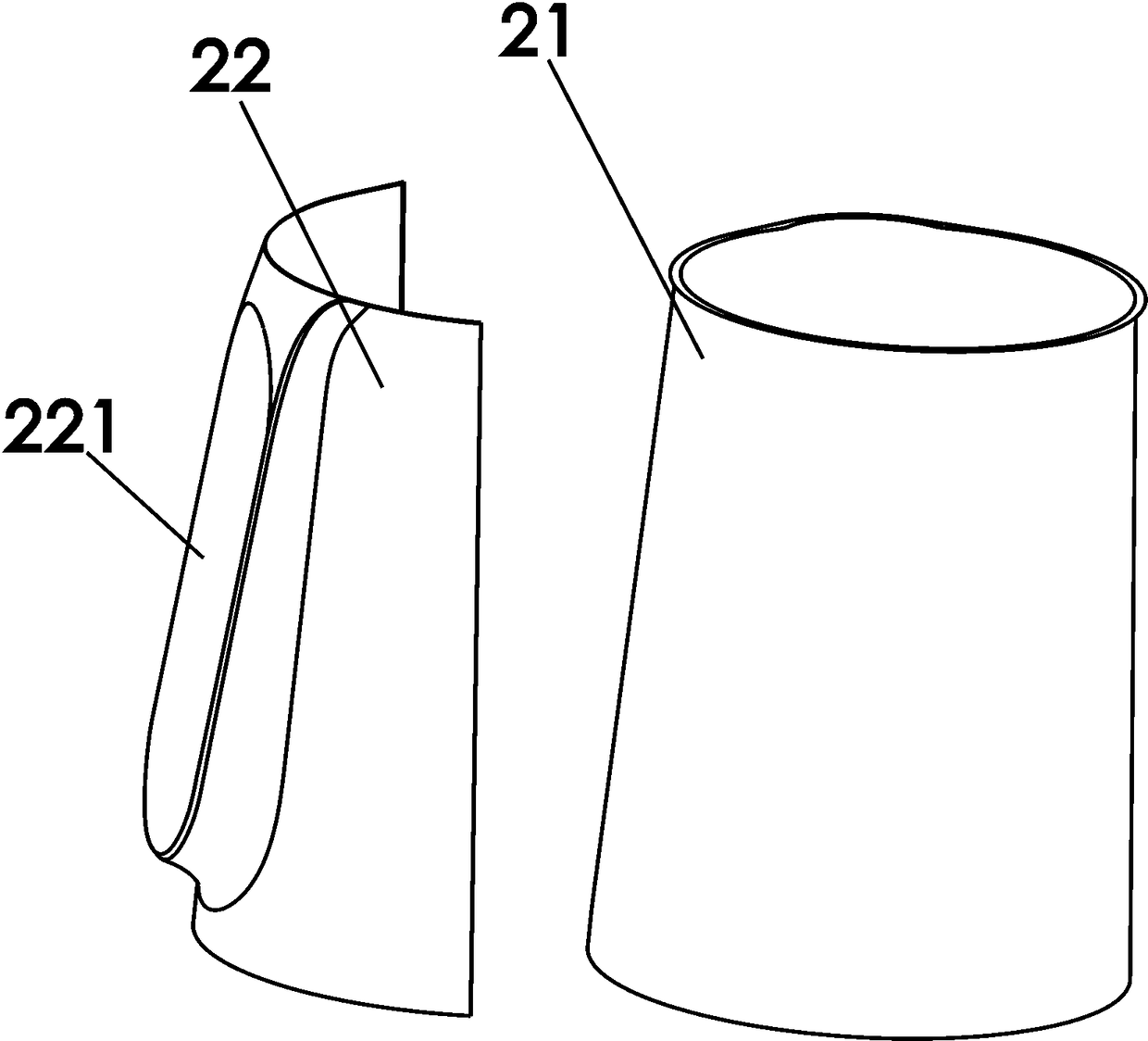
[0028] Such as figure 1 , figure 2 Shown is a schematic structural diagram of the first embodiment of the present invention. A soybean milk machine, comprising a machine head 1 and a cup body 2, the machine head 1 is installed on the cup body 2, and the cup body 2 includes a cup body base 21 and a cup body shell 22 arranged outside the cup body base 21 , the cup housing 22 is provided with an outwardly protruding interface interaction part, an interface interaction area 221 is formed on the outside of the interface interaction part, and an accommodating cavity for accommodating a circuit board is formed on the inside of the interface interaction part (located at the interface interaction area, not marked in the figure).

[0029] In this embodiment, the cup body base 21 is a single-layer metal cup body, the cup body shell 22 is an interface mounting plate with a plate-like structure fixed on the outside of the metal cup body, and the interface interaction area 221 is located...

Embodiment 2

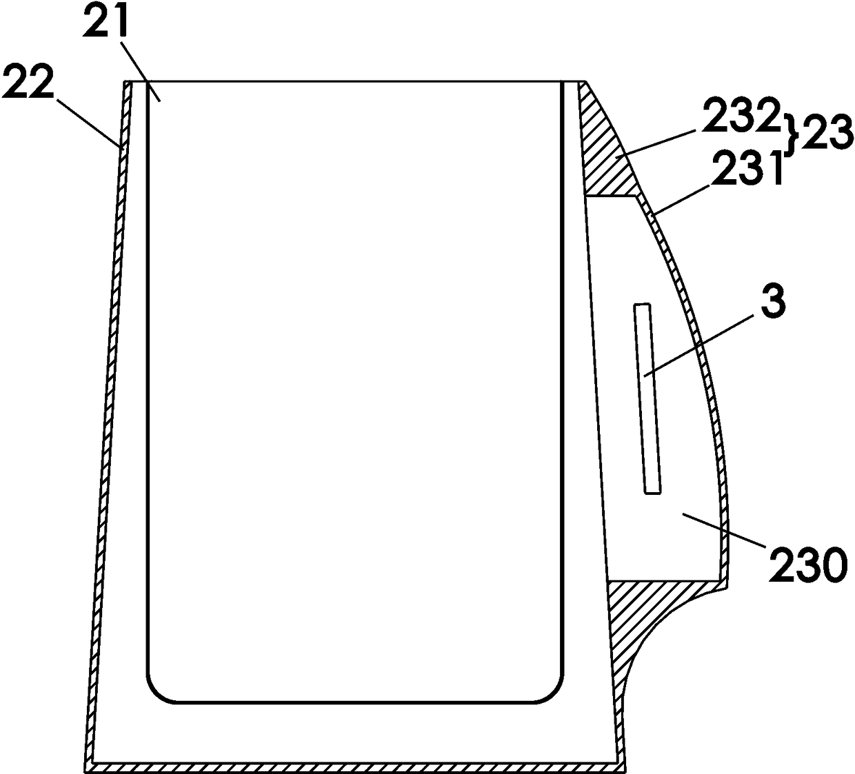
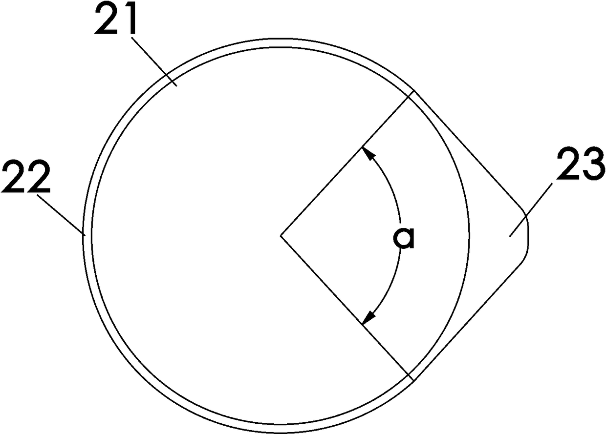
[0033] Such as image 3 , Figure 4 Shown is a schematic structural diagram of the second embodiment of the present invention. The difference between this embodiment and Embodiment 1 is that in this embodiment, the cup base 21 is a metal cup, and the cup shell 22 is a barrel-shaped cup shell set on the outside of the metal cup. The interface interaction part 23 includes an interface interaction board 231 and a raised seat 232 connected with the interface interaction board 231 , the interface interaction area is located on the interface interaction board 231 , wherein the interface interaction board 231 and the raised seat 232 are integrally injection molded. And the circuit board 3 is disposed in the receiving cavity 230 formed by the interface interaction board 231 and the raised seat 232 .

[0034] For this embodiment, of course, the interface interaction board can also be a split structure with the raised seat, for example: the interface interactive board can be fixed on ...

Embodiment 3

[0038] Such as Figure 5 , Figure 6 Shown is a schematic structural view of the third embodiment of the present invention. The difference between this embodiment and the second embodiment is that: in this embodiment, the raised seat 232 is set through the outer shell of the cup body, and the outer edge of the raised seat 232 is provided with a through hole 2320, and the interface interaction plate 231 is fixed on the through hole. mouth 2320, and seal the through opening 2320, and an isolation plate 4 is also arranged in the interlayer between the metal cup body and the interface interaction part, and the isolation plate 4 is surrounded by the accommodating cavity 230 to form a seal for the circuit board 3 cavity.

[0039]In this embodiment, the bulging height of the interface interaction part is C, wherein C is required to be at least greater than 10 mm. Because, for this embodiment, the inner side of the interface interaction part is to form the accommodating cavity for ...


PUM

PropertyMeasurementUnit
Heightaaaaaaaaaa

Abstract

The invention relates to kitchen appliances, in particular to a soybean milk machine. The machine comprises a cup body, the cup body is characterized by comprising a cup body base and a cup body shelldisposed outside the cup body base, an interface interaction portion protruding outward is arranged on the cup body shell, an interface interaction region is formed outside the interface interactionportion, and an accommodating cavity for accommodating a circuit board is formed inside the interface interaction portion. Compared with the prior art, the machine provides more convenience for consumers to observe and use the soybean milk machine, a machine head is liberated for the soybean milk machine with a motor arranged on the upper portion, no control device is needed inside the machine head, the space inside the machine head is reduced, the thickness of the machine head can be further reduced, the weight of the whole machine is correspondingly reduced, and elderly and children can moreconveniently lift the machine head.

Description

technical field [0001] The invention relates to small kitchen appliances, in particular to a soybean milk maker. Background technique [0002] The existing soybean milk machine includes a machine head and a cup body, and the top surface of the machine head is an operation / display interface, and a control device for controlling the operation / display interface is arranged in the machine head, and at the same time, electrical components such as motors are also installed in the machine head , so the space in the machine head needs to be set larger to take advantage of the installation of these electrical components and effective heat dissipation, which results in a thicker machine head and a heavier overall weight of the machine head, not only the appearance is not beautiful, but also For the elderly and children, the heaviness of lifting the nose is stronger. Secondly, when consumers use the soymilk maker, they need to get close to the top of the soymilk maker to be able to ...

Claims


Application Information

Patent Timeline
IPC IPC(8): A47J43/07
CPCA47J43/07A47J2043/0738
Inventor 王旭宁张志国薛东伟李玉涛
Owner JOYOUNG CO LTD
Why Eureka
Try Eureka