Environment-friendly garbage treatment device

A garbage disposal device and environmentally friendly technology, applied in the direction of presses, manufacturing tools, etc., can solve the problems that the compressor does not have the function of draining sewage, no parts for fixing garbage, and the compression effect is not good, and achieves simple structure and fast compression speed. , The effect of low maintenance cost

Inactive Publication Date: 2018-07-06
广州凯燃环保工程技术有限公司
View PDF3 Cites 0 Cited by
  • Summary
  • Abstract
  • Description
  • Claims
  • Application Information

AI Technical Summary

Problems solved by technology

At present, some common garbage compressors have slow compression speed, expensive price, poor compression effect, and most of them have no fixed parts for garbage, which is prone to slippage during the garbage compression process, and these compressors basically do not have the function of sewage discharge. It flows directly to the ground, which is very unsanitary

Method used


Image

  • Environment-friendly garbage treatment device
  • Environment-friendly garbage treatment device
  • Environment-friendly garbage treatment device

Examples


Embodiment Construction

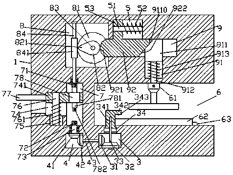
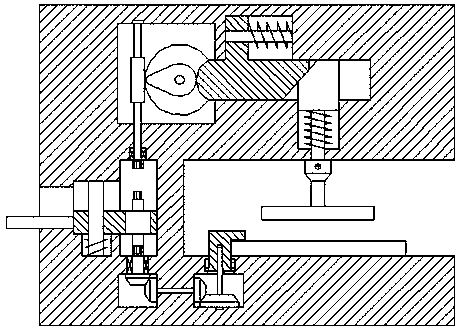
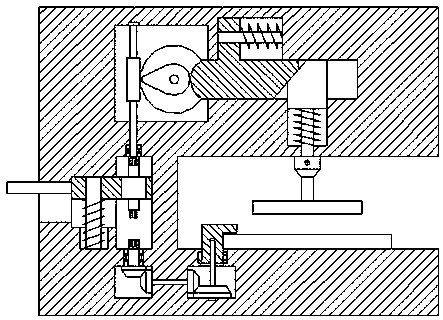
[0026] Such as Figure 1-Figure 7As shown, an environmentally friendly garbage disposal device of the present invention includes a frame body 1, a compression groove 6 is provided inside the right side of the frame body 1, and a compression groove 6 is provided inside the frame body 1 on the left side of the compression groove 6. A variable chamber 7, the upper and lower sides of the variable chamber 7 are respectively provided with a first internal helical thread locking shaft 71 and a second internal helical thread locking shaft 72, and the left side of the variable chamber 7 is provided with a first sliding groove 74 , the bottom of the first sliding connection groove 74 is provided with a recessed groove 75, and a first guide rod 76 is provided between the bottom of the recessed groove 75 and the top of the first sliding connection groove 74, and on the first guide rod 76 A first sliding block 741 extended to the right is slidably connected, and the outer surface of the fi...


PUM


Abstract

The invention discloses an environment-friendly garbage treatment device which comprises a frame. A compression groove is formed in the right side face of the frame. A change cavity is formed in the position, on the left side and the right of the compression groove, in the frame. A first inner spiral locking shaft and a second inner spiral locking shaft are arranged on the upper side and the lowerside of the change cavity correspondingly. A first sliding groove is formed in the left side of the change cavity. A sunken groove is formed in the bottom of the first sliding groove. A first guide rod is arranged between the bottom of the sunken groove and the top of the first sliding groove. A first sliding block extending rightwards is in sliding connection to the first guide rod. The outer surface of the position, at the bottom of the first sliding block, of the first guide rod is provided with a first spring ring. The extending part of the right side of the first sliding block stretchesinto the change cavity and is in sliding fit with the right side wall of the change cavity. A motor is arranged at the position, in the change cavity, in the first sliding block. Conveying shafts arearranged at the upper side end and the lower side end of the motor. A conveying cavity is formed in the position, above the change cavity, in the frame. The environment-friendly garbage treatment device is simple in structure, convenient to operate, low in manufacturing and maintaining cost, high in compression speed, high in stability and good in compression quality, sewage is drained reasonably,and cleanliness and sanitation are achieved.

Description

technical field [0001] The invention relates to the technical field of environmental protection, in particular to an environmentally friendly garbage disposal device. Background technique [0002] With the progress of society and the improvement of people's living standards, people pay more and more attention to environmental protection issues. Among them, the problem of garbage disposal is a hot spot that people pay attention to. Improper garbage disposal will pollute water sources and soil, and seriously endanger the living environment of human beings. After the garbage is sorted, many recyclables need to be compressed, such as cardboard, scrap metal and so on. At present, some common garbage compressors have slow compression speed, expensive price, poor compression effect, and most of them have no fixed parts for garbage, which is prone to slippage during the garbage compression process, and these compressors basically do not have the function of sewage discharge. It flo...

Claims


Application Information

Patent Timeline
Patent Type & Authority Applications(China)
IPC IPC(8): B30B9/30B30B15/00
CPCB30B9/30B30B9/3003B30B15/0076
Inventor 袁兴芳
Owner 广州凯燃环保工程技术有限公司
Why Eureka
Try Eureka