Inner-gear-type non-cooperative target locking mechanism

A technology of non-cooperative target and locking mechanism, which is applied in the field of locking mechanism and internal gear type non-cooperative target locking mechanism, which can solve problems such as poor connection stiffness, target escape, difficulty in ensuring target stability and attitude accuracy, etc. , to achieve the effect of ensuring stability and preventing escape

Active Publication Date: 2018-07-06
HARBIN INST OF TECH
View PDF7 Cites 2 Cited by
  • Summary
  • Abstract
  • Description
  • Claims
  • Application Information

AI Technical Summary

Problems solved by technology

[0003] The purpose of the present invention is to solve the problems that the existing non-cooperative target docking mechanism is difficult to ensure the stability of the target and the accuracy of the posture after capturing the target, the connection stiffness is poor, and there is a risk of target escape, and then provide an internal gear The non-cooperative target locking mechanism can realize the capture and release of the target, ensure the stability of the target and the accuracy of the posture, and effectively prevent escape

Method used


Image

  • Inner-gear-type non-cooperative target locking mechanism
  • Inner-gear-type non-cooperative target locking mechanism
  • Inner-gear-type non-cooperative target locking mechanism

Examples


specific Embodiment approach 1

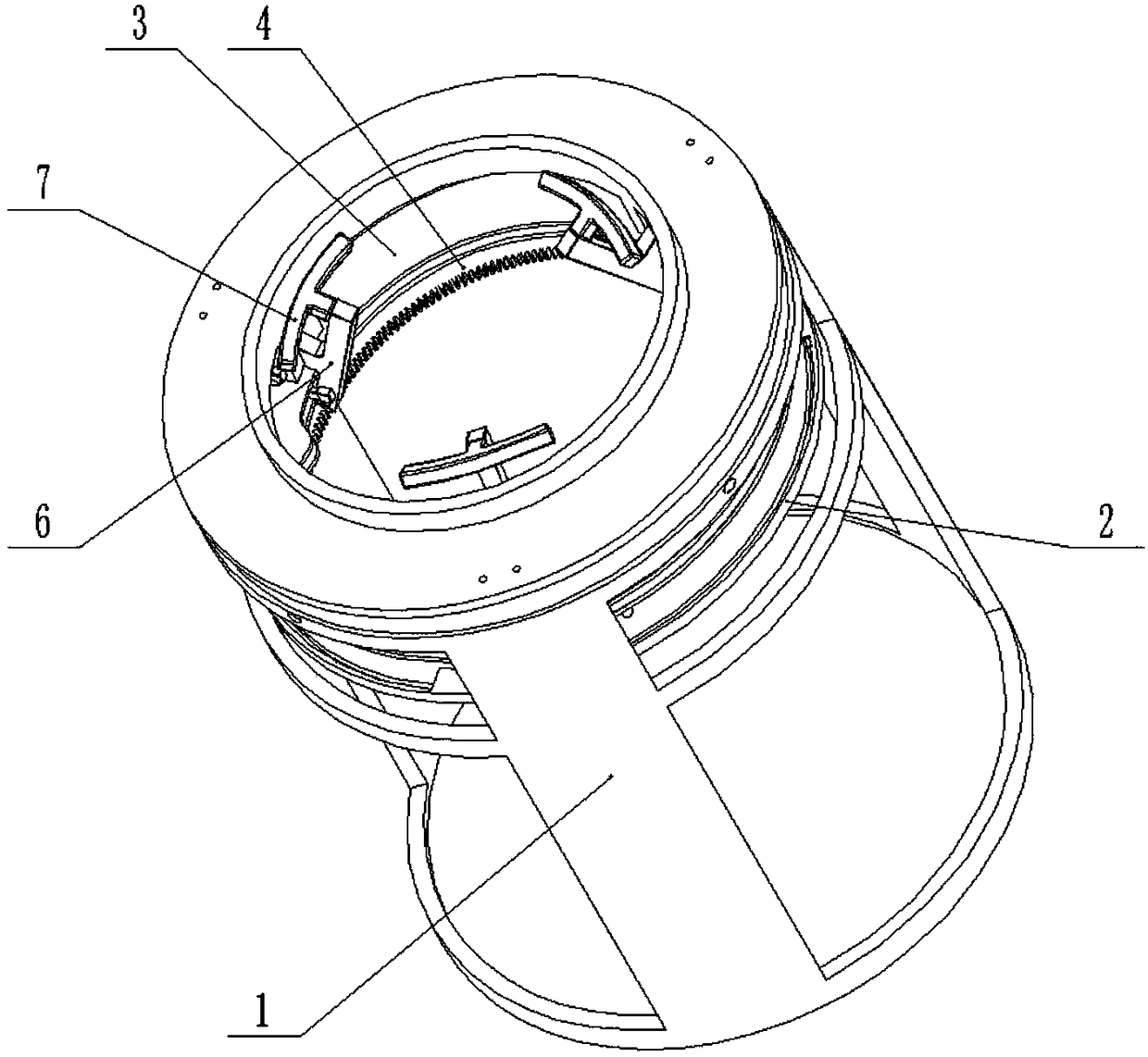
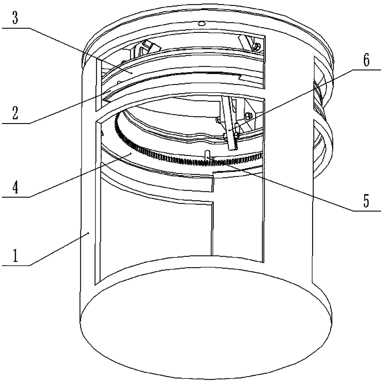
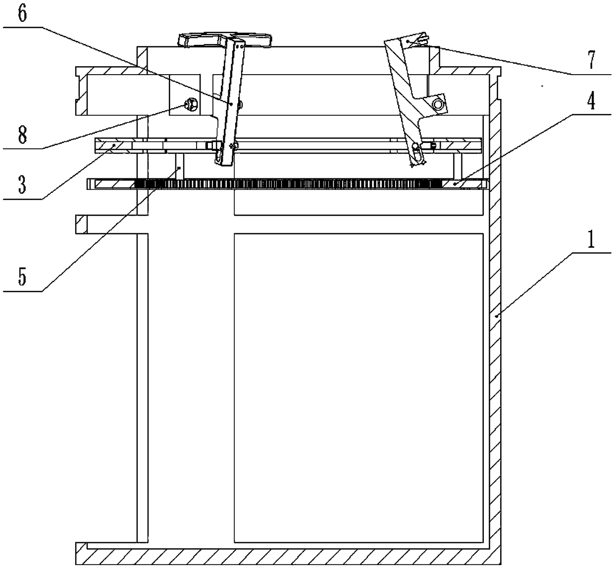
[0030] Combine below Figure 1-13 Describe this embodiment, an internal gear type non-cooperative target locking mechanism, including a support housing 1, a bearing bush 2, a ring assembly 3, an inner ring gear 4, a connecting column 5, a locking link 6, a pressure block 7, Connect the screw rod 8 and the torsion spring, the bearing bush 2 is fixedly connected to the middle and upper end of the inner wall of the supporting shell 1, the inner ring gear 4 is rotatably connected in the bearing bush 2, and the upper end of the inner ring gear 4 passes through a plurality of connecting columns 5 The ring assembly 3 is fixedly connected, and the upper end inside the supporting shell 1 is fixedly connected with multiple sets of lugs 1-1, each set of lugs 1-1 is hingedly connected to the middle end of the locking link 6 through a connecting screw 8 , the connecting screw 8 is sleeved with a torsion spring, the two ends of the torsion spring are respectively connected to the supporting...

specific Embodiment approach 2

[0031] Combine below Figure 1-13 Describe this embodiment, this embodiment will further explain the first embodiment, the pressure block 7 is an arc-shaped structure, and the middle end of the outer side of the pressure block 7 is provided with a spring pin, which can realize locking during the locking process. self-centering function.

specific Embodiment approach 3

[0032] Combine below Figure 1-13 Describe this embodiment, this embodiment will further explain Embodiment 1, the support shell 1 is a cylindrical structure, the lower end of the support shell 1 is provided with a plurality of briquetting grooves 1-2, the briquetting The number of grooves 1-2 is the same as the number of pressure blocks 7; multiple pressure block grooves 1-2 of one locking mechanism can be mated with multiple pressure blocks 7 of another locking mechanism to achieve multi-joint connection.


PUM


Abstract

The invention belongs to the technical field of spaceflight, and particularly relates to an inner-gear-type non-cooperative target locking mechanism. The inner-gear-type non-cooperative target lockingmechanism comprises a supporting shell, a bearing bush, a circular ring assembly, an inner toothed ring, multiple connecting pillars, locking connecting rods, pressing blocks, connecting screws and torsional springs, wherein the bearing bush is fixedly connected to the middle upper end of the inner wall of the supporting shell, the inner toothed ring is rotatably connected into the bearing bush,the upper end of the inner toothed ring is fixedly connected with the circular ring assembly through the connecting pillars, the upper end inside the supporting shell is fixedly connected with multiple lugs, all the lugs are hinged to the middle ends of the locking connecting rods through the connecting screws respectively, the connecting screws are sleeved with the torsional springs, the two endsof each torsional spring are connected with the supporting shell and the locking connecting rods respectively, the pressing blocks are fixedly connected to the upper ends of the locking connecting rods, the lower ends of the locking connecting rods are slidably connected with the inner side of the circular ring assembly, and the inner side of the circular ring assembly is fixedly connected with multiple convex lugs. By means of the inner-gear-type non-cooperative target locking mechanism, catching and releasing of a target can be achieved, and the stability of the target and the accuracy of the attitude are guaranteed.

Description

technical field [0001] The invention belongs to the field of aerospace technology, and in particular relates to a locking mechanism, more specifically an internal gear type non-cooperative target locking mechanism. Background technique [0002] The non-cooperative target docking technology is different from the cooperative target docking technology. Its docking target is a satellite without a specific docking interface. Generally, the AKM nozzle of the satellite's apogee recoil engine is selected as the docking interface. Currently designed docking mechanisms for non-cooperative targets lack locking mechanisms, poor connection stiffness, and poor capture reliability. Contents of the invention [0003] The purpose of the present invention is to solve the problems that the existing non-cooperative target docking mechanism is difficult to ensure the stability of the target and the accuracy of the posture after capturing the target, the connection stiffness is poor, and there ...

Claims


Application Information

Patent Timeline
Patent Type & Authority Applications(China)
IPC IPC(8): B64G1/64
Inventor 李隆球周德开徐勇杰余泽顺俞中委初广昊
Owner HARBIN INST OF TECH
Why Eureka
Try Eureka