
Ventilation transport box equipment assembly

A technology for transportation boxes and equipment, which is applied in the direction of transportation and packaging, special packaging objects, bottle/can parts, etc., which can solve the problems of shortened shelf life, easy bumps, and perishability, etc., and achieve good shock absorption effect and shock absorption Good effect, good breathability effect

Inactive Publication Date: 2018-07-06
合肥天之通电子商务有限公司
View PDF7 Cites 4 Cited by
  • Summary
  • Abstract
  • Description
  • Claims
  • Application Information

AI Technical Summary

Problems solved by technology

[0002] At present, the transport boxes mainly include plastic boxes, foam boxes, etc. The transport boxes have the functions of heat preservation and freshness preservation. However, the transport boxes are prone to bumps during transportation, and the goods are prone to damage during long-term transportation, especially during the transportation of vegetables and fruits. Among them, fruits and vegetables are extremely perishable in the state of lack of gas exchange and damage after collision, which greatly shortens their shelf life, and if the rotten fruits and vegetables are not handled in time, it is easy to cause a wide range of fruits and vegetables Deterioration; therefore, during the transportation of the transport box, how to reduce the collision caused by bumps as much as possible, improve the shock resistance of the transport box, and ensure the air permeability of the goods during transportation are all problems that need to be solved

Method used


Image

  • Ventilation transport box equipment assembly
  • Ventilation transport box equipment assembly

Examples


Embodiment Construction

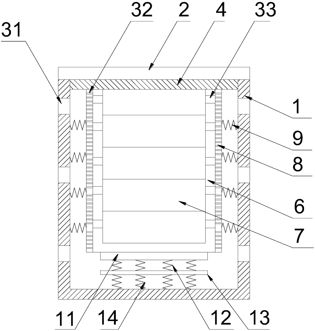
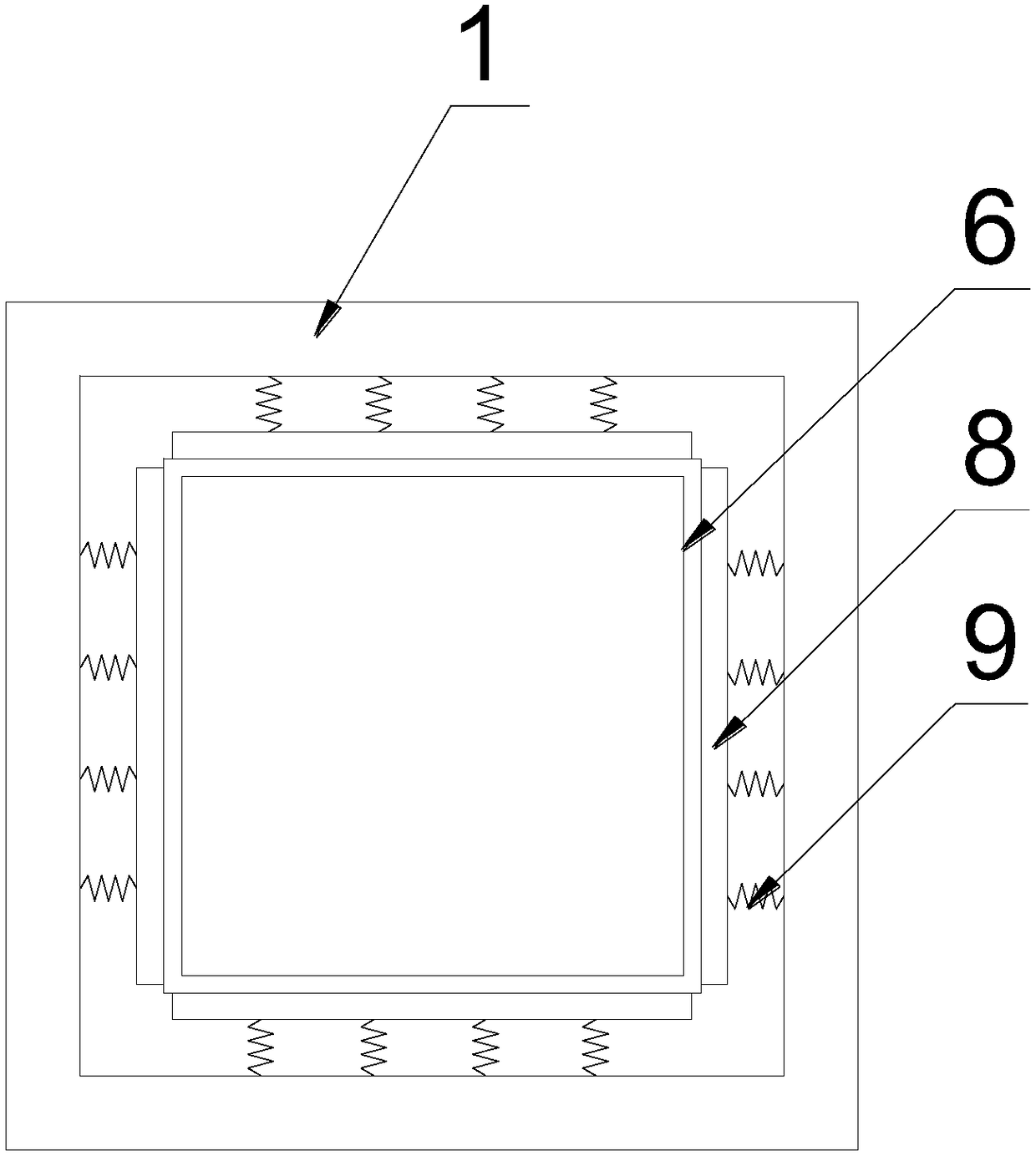
[0017] Such as Figure 1-2 as shown, figure 1 It is a structural schematic diagram of a ventilated transport box equipment assembly proposed by the present invention, figure 2 It is a schematic diagram of part of the structure of the air-permeable transport box equipment assembly proposed by the present invention.

[0018] refer to Figure 1-2 , a kind of air-permeable transport box equipment assembly that the present invention proposes, comprises outer box 1, box cover 2, inner box 6, transport box 7, baffle plate 8, spring 9, first bottom plate 11, first compression spring 12, second Base plate 13 and second compression spring 14;

[0019] The outer box 1 and the box cover 2 are set together, and the space between the outer box 1 and the box cover 2 is not sealed; the inner side of the box cover 2 is provided with a cushion 4; the inner box 6 is placed inside the outer box 1, and the inner box 6 is placed inside the transport box 7; A baffle plate 8 is arranged around t...


PUM


Abstract

The invention discloses a ventilation transport box equipment assembly which comprises an outer box, a box cover, an inner box, a transport box, baffles, springs, a first bottom plate, first pressuresprings, a second bottom plate and second pressure springs. The outer box and the box cover are arranged in a cooperation manner, and the space between the outer box and the box cover is not sealed. The inner box is put in the outer box, and the transport box is put in the inner box. The baffles are arranged on the periphery of the inner box, one face of each baffle is attached to the inner box, the springs are mounted on the other faces of the baffles, and the other ends of the springs are connected with the inner wall of the outer box. First ventilation holes are formed in a box body of theouter box, second ventilation holes are formed in the baffles, third ventilation holes are formed in a box body of the inner box, and the diameter of the second ventilation holes is smaller than thatof the third ventilation holes. The first bottom plate is arranged at the bottom of the inner box in an attached manner, the second bottom plate is arranged below the first bottom plate, the multiplefirst pressure springs are mounted between the first bottom plate and the second bottom plate, and the multiple second pressure springs are mounted between the second bottom plate and the bottom of the outer box. The ventilation transport box equipment assembly is good in shock absorption effect and good in ventilation performance, and goods are prevented from being damaged.

Description

technical field [0001] The invention relates to the field of cargo transport equipment, in particular to an air-permeable transport box equipment component. Background technique [0002] At present, the transport boxes mainly include plastic boxes, foam boxes, etc. The transport boxes have the functions of heat preservation and freshness preservation. However, the transport boxes are prone to bumps during transportation, and the goods are prone to damage during long-term transportation, especially during the transportation of vegetables and fruits. Among them, fruits and vegetables are extremely perishable in the state of lack of gas exchange and damage after collision, which greatly shortens their shelf life, and if the rotten fruits and vegetables are not handled in time, it is easy to cause a wide range of fruits and vegetables Deterioration; therefore, during the transportation of the transport box, how to reduce the collision caused by bumps as much as possible, improve...

Claims


Application Information

Patent Timeline
Patent Type & Authority Applications(China)
IPC IPC(8): B65D81/07B65D81/18B65D81/26B65D25/00
CPCB65D81/07B65D25/00B65D81/18B65D81/263B65D81/266
Inventor 唐成奎
Owner 合肥天之通电子商务有限公司
Learn More