Crane period anti-swing control method

A control method and crane technology, applied in the directions of load hanging components, transportation and packaging, can solve the problems of high cost and complex anti-sway control system, and achieve the effects of low cost, anti-sway control and easy engineering realization.

Inactive Publication Date: 2018-07-06
NANJING UNIV OF AERONAUTICS & ASTRONAUTICS
View PDF8 Cites 10 Cited by
  • Summary
  • Abstract
  • Description
  • Claims
  • Application Information

AI Technical Summary

Problems solved by technology

[0006] The purpose of the present invention is to solve the problem that the existing electronic or mechanical anti-sway control system of the crane

Method used


Image

  • Crane period anti-swing control method
  • Crane period anti-swing control method
  • Crane period anti-swing control method

Examples


Embodiment 1

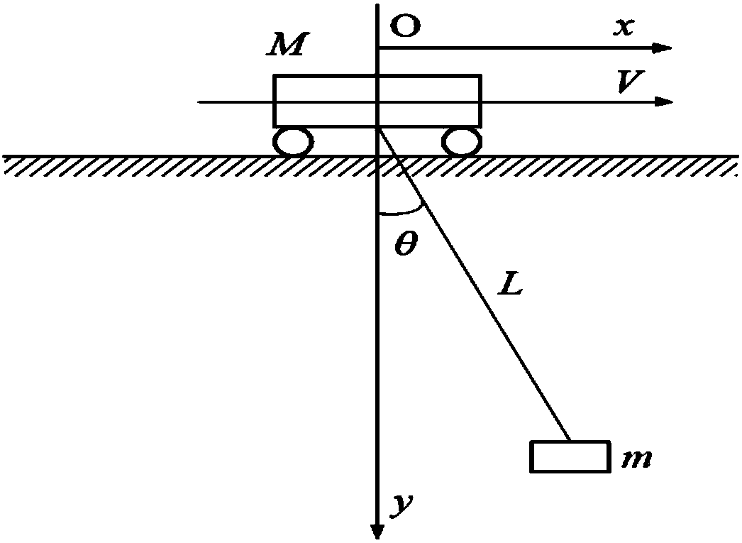
[0035] like figure 1 , 3 , 4 shown.

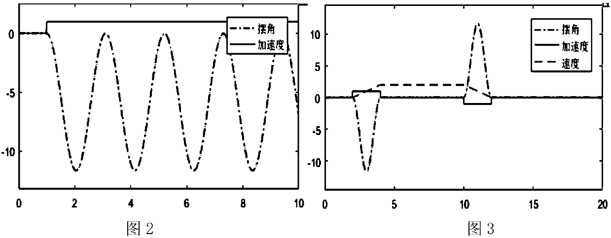
[0036] A crane cycle anti-sway control method, the key of which is to divide the hoisting process of the crane into a constant acceleration process, a constant speed process, and a constant deceleration process, and the load swing angle is zero during the constant speed process and stop; a as input, the acceleration time is one or an integer number of periods nT, T is the swing period, n is a natural number, acceleration a=garctan(θ max / 2), to meet the maximum allowable swing angle θ max Constraint conditions; in the process of constant speed, the trolley with V 匀 = naT hoisting at a constant speed; the constant deceleration process is the inverse process of the constant acceleration process, that is, the trolley takes the acceleration-a as input, and the duration is the same as the acceleration time, for example figure 1 shown.

[0037] Take the car movement as an example. refer to image 3 , Figure 4 , give the trolley a consta...

Embodiment 2

[0040] like figure 1 , 5 shown.

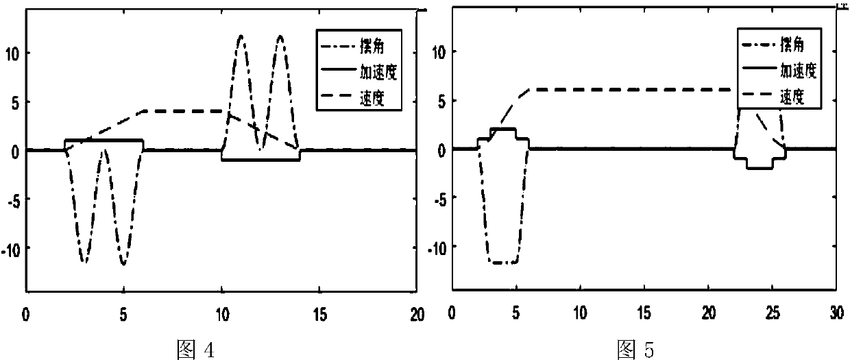
[0041]A crane cycle anti-sway control method, the key of which is to divide the hoisting process of the crane into an acceleration process, a constant speed process, and a deceleration process. The expected constant speed value plans the specific control process; the acceleration process can be divided into T 1 , T 2 , T 3 Three stages: where T 1 Phase and T 3 The stage car input is symmetrical, and the acceleration and duration are the same, that is, a 1 =a 3 ,T 1 =T 3 =T / 2, T is the swing period; acceleration a 1 =garctan(θ max / 2), to meet the maximum allowable swing angle θ max constraints; T 2 Stage acceleration a 2 =garctanθ max , at this time there is a 2 = 2a 1 / (1-a 1 2 / g 2 ), the duration is adjusted according to the desired constant speed; the deceleration process is the inverse process of the acceleration process, such as figure 1 shown.

[0042] refer to Figure 5 , the whole lifting process still includes ...


PUM


Abstract

A crane period anti-swing control method is characterized in that the crane hoisting process is divided into a constant acceleration process, a constant speed process and a constant deceleration process, and the load swing angle is zero in the constant speed process and during stopping; in the constant acceleration process, a trolley adopts the accelerated speed a as the input, the acceleration duration is a period or an integral number of periods nT, T is the swing period, n is a natural number, the accelerated speed a=garctan (theta<max>/2), and the constraint condition of the maximum allowable swing angle theta<max> is met; in the constant speed process, the trolley carries out hoisting at the constant speed of V<constant>=naT; and the constant deceleration process is the inverse process of the constant acceleration process, that is, the trolley adopts the accelerated speed -a as the input, and the lasting duration is the same as the acceleration duration. The crane period anti-swing control method starts with the kinematics, it can be theoretically achieved that the load swing angle is zero during constant-speed running and stopping, no swing angle senor is needed, engineeringimplementation is easy, and cost is low. When the limiting conditions such as the swing angle, the expected constant speed and the stroke are given, the specific acceleration and deceleration processes meeting all expected conditions can be planned easily.

Description

technical field [0001] The invention relates to a motion control method, in particular to a motion control method for a crane cart and a trolley, in particular to a crane cycle anti-sway control method. Background technique [0002] Cranes are widely used in factory production and modern logistics. Automation, intelligence and efficiency are important development directions of modern crane control. [0003] The load of traditional cranes will sway continuously during the operation of large and small vehicles, which seriously affects the safety and work efficiency of crane cargo lifting; at this time, the control of load swaying depends entirely on the experience of the operator, and there are many influencing factors, often the actual effect Poor or inefficient. [0004] With the development of modern logistics, the research and technology of crane anti-sway control are getting more and more attention. The crane anti-sway technologies currently on the market mainly include...

Claims


Application Information

Patent Timeline
IPC IPC(8): B66C13/06
CPCB66C13/06
Inventor 游有鹏白心阳杨雪峰游皓元
Owner NANJING UNIV OF AERONAUTICS & ASTRONAUTICS
Why Eureka
Try Eureka