Marine knuckle crane

A crane and marine technology, applied in cranes and other directions, can solve the problems of small load capacity, large space occupation, affecting work efficiency, etc., and achieve the effect of small bearing capacity requirements, small oil cylinder bearing capacity, and improved hull inclination.

Inactive Publication Date: 2018-07-06
JIANGSU MASADA HEAVY INDS
View PDF6 Cites 7 Cited by
  • Summary
  • Abstract
  • Description
  • Claims
  • Application Information

AI Technical Summary

Problems solved by technology

[0002] A marine crane is a machine used for lifting, loading and unloading cargo on sea transport ships. Generally, a crane is installed on a large cargo ship, which includes a base welded on the base of the ship's deck and a column fixed on the base. A telescopic boom controlled by an oil cylinder is hinged at the top of the telescopic boom, and a hoisting winch is installed at the lower end of the telescopic boom. For a crane with this mechanical structure, since the base and the column are fixedly connected and the pump station is installed on the deck, and the boom cannot be retracted, Therefore, the telescopic boom can only be a one-way operation of extending forward and retracting, which is not only inconvenient to use and affects work efficiency, but also takes up a lot of space and has a large windward area, which affects the speed of the hull.
[0003] Although the crane of this structure has no practical effect on large ships, on some small ships, due to the small load capacity of the ship itself, this kind of non-foldable crane not only increases its occupation area, but also has a large windward surface of the boom that extends horizontally. , not only affects the speed, but also causes the hull to tilt

Method used


Image

  • Marine knuckle crane
  • Marine knuckle crane

Examples


Embodiment Construction

[0016] The technical solutions of the embodiments of the present invention will be clearly and completely described below in conjunction with the accompanying drawings of the present invention.

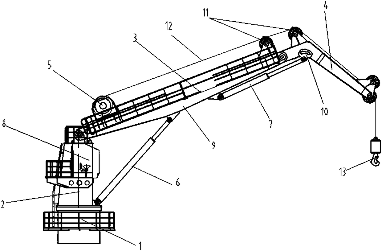
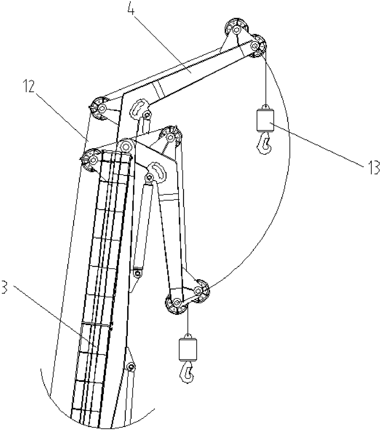
[0017] Such as Figure 1~2 As shown, a marine folding arm crane disclosed in the present invention includes a base 1, a tower body 2, a main boom 3, an auxiliary boom 4, a hoisting winch 5, a first oil cylinder 6 and a second oil cylinder 7, The base 1 is fixed on the side of the ship, and the tower body 2 is fixed on the base 1, and the front end of the tower body is provided with a cab 8, the main boom is hinged on the top of the tower body, and its bottom surface has a triangular mounting plate 9. The cylinder body end of the first oil cylinder 6 is hinged to the tower body below the cab, and the telescopic rod is hinged to the triangular vertex of the triangular plate. The first oil cylinder controls the folding of the main boom, and the auxiliary boom 4 is a folding The bending ...


PUM


Abstract

The invention discloses a marine knuckle crane which comprises a base, a tower body, a main lazy arm, an auxiliary lazy arm, a lifting winch, a first oil cylinder and a second oil cylinder. The base is fixed to the side of a ship, the tower body is fixed to the base, and a cab is arranged at the front end of the tower body. The main lazy arm is hinged to the upper end of the tower body. The two ends of the first oil cylinder are hinged to the tower body and the bottom face of the main lazy arm correspondingly. The main lazy arm is controlled by the first oil cylinder to be folded. The auxiliary lazy arm is of a bent structure, and one end of the auxiliary lazy arm is hinged to the front end of the main lazy arm. The two ends of the second oil cylinder are hinged to the bottom face of the main lazy arm and the bent point of the auxiliary lazy arm. The auxiliary lazy arm is controlled to be supported or retract. The lifting winch is mounted on the upper end face of the main lazy arm, andsteel wire rope guide is carried out through a guide wheel mounted on the main lazy arm and the auxiliary lazy arm.

Description

technical field [0001] The invention relates to a crane, in particular to a marine folding arm crane. Background technique [0002] A marine crane is a machine used for lifting, loading and unloading cargo on sea transport ships. Generally, a crane is installed on a large cargo ship, which includes a base welded on the base of the ship's deck and a column fixed on the base. A telescopic boom controlled by an oil cylinder is hinged at the top of the telescopic boom, and a hoisting winch is installed at the lower end of the telescopic boom. For a crane with this mechanical structure, since the base and the column are fixedly connected and the pump station is installed on the deck, and the boom cannot be retracted, So the telescopic boom can only be the one-way operation of stretching out and retracting forward, which is not only inconvenient to use and affects work efficiency, but also takes up a lot of space and has a large windward area, which affects the speed of the hull. ...

Claims


Application Information

Patent Timeline
Patent Type & Authority Applications(China)
IPC IPC(8): B66C23/62B66C23/693
CPCB66C23/62B66C23/705
Inventor 黄志峰陆飞沈佳加
Owner JIANGSU MASADA HEAVY INDS
Why Eureka
Try Eureka