Supercharge Your Innovation With Domain-Expert AI Agents!

Window frame angle part connecting device

A corner connection and window frame technology, which is applied to windows/doors, building components, buildings, etc., can solve the problems of inconvenient assembly and disassembly of window frames, easy deformation, time-consuming and labor-intensive problems

Pending Publication Date: 2018-07-06
毕建峰
View PDF4 Cites 0 Cited by
  • Summary
  • Abstract
  • Description
  • Claims
  • Application Information

AI Technical Summary

Problems solved by technology

[0002] see Figure 4 , for the connection between two adjacent window frames 21, the traditional installation method is to glue or use fasteners such as screws to connect. Such installation is not only time-consuming and labor-intensive, but also prone to loosening. A connecting fastener suitable for the screen window frame
In addition, there are also corners of two window frames 21 that are connected by connectors, but the existing corner connectors of window frames are easy to loosen due to their unreasonable structural design. Easy to deform, it is inconvenient to assemble and disassemble the window frame during the assembly process, and the work efficiency of assembling the window frame is low

Method used


Image

  • Window frame angle part connecting device
  • Window frame angle part connecting device
  • Window frame angle part connecting device

Examples


Embodiment Construction

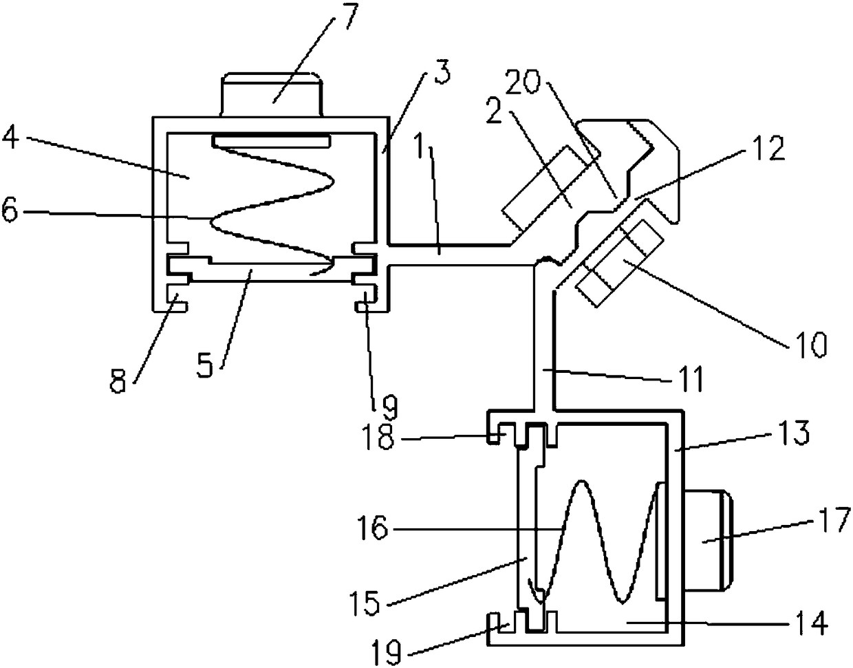
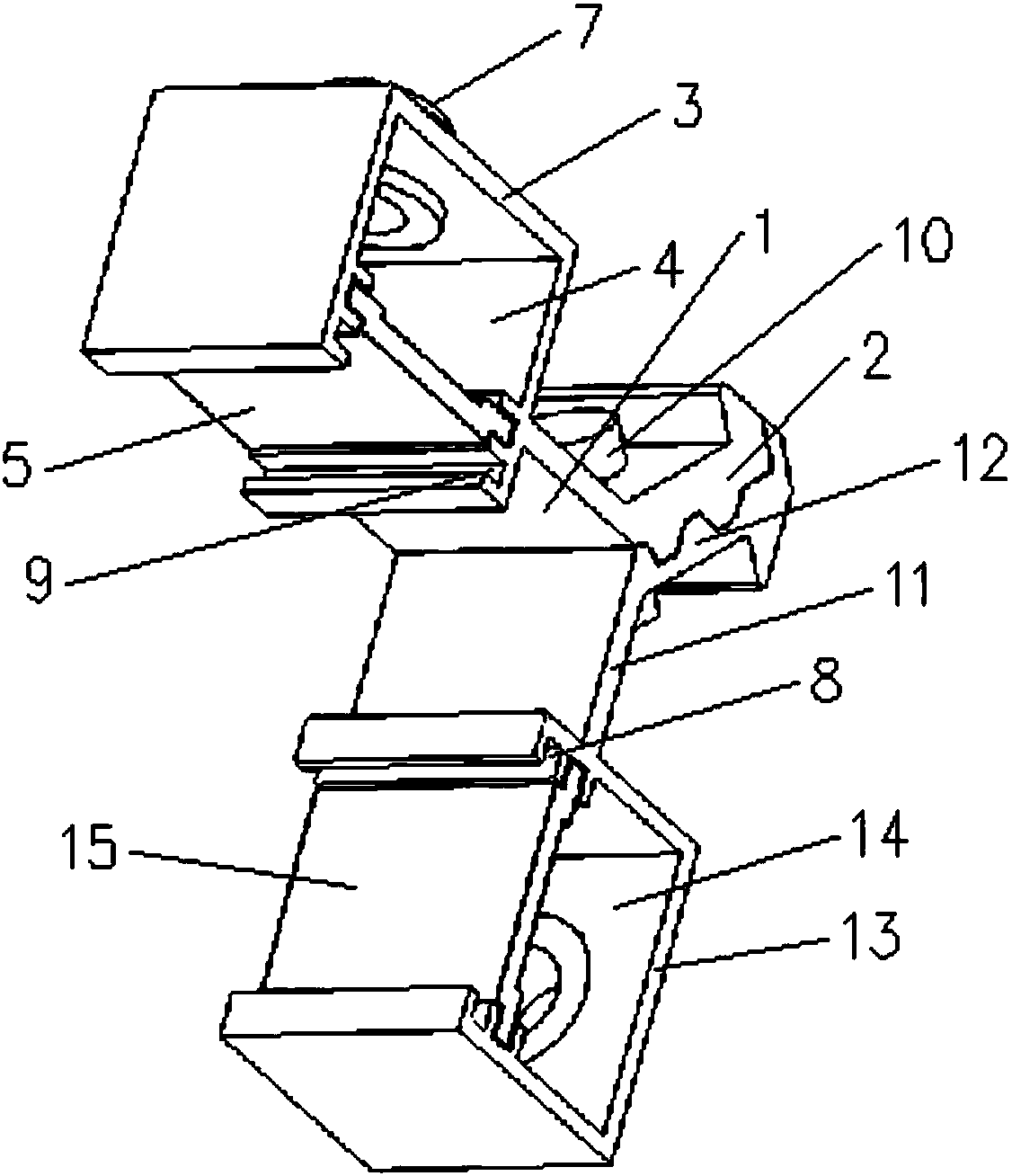
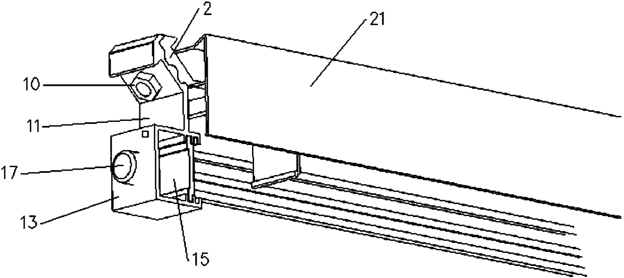
[0022] Such as figure 1 and figure 2 As shown, the window frame corner connection device of the present invention includes a horizontal plate 1 and a vertical plate 11, the plate surface of the horizontal plate 1 is located in the horizontal direction, the right end of the horizontal plate 1 is connected with the left end of the sloping plate 2 as a whole, and the slanting plate The board surface of the plate 2 protrudes obliquely upward from left to right, the left end of the horizontal plate 1 is connected with the right end of the block 3 as a whole, the top end surface of the block 3 is located in the horizontal direction, and the lower end surface of the block 3 is provided along the front and rear direction. The vertical pin placement groove 4, the left side wall of the vertical pin placement groove 4 is provided with a left card slot 8 along the front and rear direction, and the right side wall of the vertical pin placement slot 4 is provided with a right card slot al...


PUM


Abstract

The invention discloses a window frame angle part connecting device. The window frame angle part connecting device comprises a transverse plate and a vertical plate. The right end of the transverse plate is connected with the left end of a transverse-inclined plate to form an integrated body. The plate surface of the transverse-inclined plate extends upwards in an inclined mode from left to right.The left end of the transverse plate is connected with the right end of a clamping block to form an integrated body. A vertical pin shaft placing groove is formed in the lower end surface of the clamping block in the front and rear directions. A left clamping groove is formed in the left side wall of the vertical pin shaft placing groove in the front and rear directions. A right clamping groove is formed in the right side wall of the vertical pin shaft placing groove in the front and rear directions. A bottom plate is arranged in the vertical pin shaft placing groove. A pressure spring is arranged on the upper portion of the bottom plate in the vertical direction. The top end of the pressure spring abuts against the bottom portion of a vertical pin shaft. The vertical pin shaft extends upwards and penetrates through the top of the clamping block. The purpose is to provide a window frame angle part connecting device which enables a connected window frame angle part to be very firm, notloosened and not deformed, has high strength and large rigidity to the connection of the window frame angle part, has convenient and quick assembly and disassembly to a window frame in the assembly process, and can greatly improve the working efficiency of the assembly of the window frame.

Description

technical field [0001] The invention relates to a window frame corner connection device. Background technique [0002] see Figure 4 , for the connection between two adjacent window frames 21, the traditional installation method is to glue or use fasteners such as screws to connect. Such installation is not only time-consuming and labor-intensive, but also prone to loosening. A connecting fastener suitable for the screen window frame. In addition, there are also corners of two window frames 21 that are connected by connectors, but the existing corner connectors of window frames are easy to loosen due to their unreasonable structural design. It is easy to deform, and it is inconvenient to assemble and disassemble the window frame during the assembly process, and the work efficiency of assembling the window frame is low. Contents of the invention [0003] The object of the present invention is to provide a method that can make the corners of the window frame to be connecte...

Claims


Application Information

Patent Timeline
IPC IPC(8): E06B3/964E06B3/968
CPCE06B3/964E06B3/968
Inventor 毕建峰毕二峰
Owner 毕建峰
Features
  • R&D
  • Intellectual Property
  • Life Sciences
  • Materials
  • Tech Scout
  • Unparalleled Data Quality
  • Higher Quality Content
  • 60% Fewer Hallucinations
Learn More