Expansion switch valve

A technology of switching valves and spools, applied in the direction of lift valves, multi-way valves, valve devices, etc., can solve problems such as damage to the internal structure of the solenoid valve, unfavorable oil return of the heat pump system, difficulty in oil return of the compressor, etc., to reduce charging Quantity, cost reduction, and simple structure

Inactive Publication Date: 2018-07-06
BYD CO LTD
View PDF6 Cites 2 Cited by
  • Summary
  • Abstract
  • Description
  • Claims
  • Application Information

AI Technical Summary

Problems solved by technology

This structure requires two tee joints and six pipelines, the structure is relatively complicated and it is not easy to install
When the solenoid valve is closed and the electronic expansion valve is used, the inlet of the electronic expansion valve is a medium-temperature and high-pressure liquid refrigerant, and the outlet of the electronic expansion valve is a low-temperature and low-pressure liquid refrigerant. Since the pipelines are connected, the inlet and outlet of the solenoid valve are also separated. The state of the refrigerant at the inlet and outlet of the electronic expansion valve is consistent, and the pressure and temperature of the refrigerant at the inlet and outlet of the solenoid valve are different, which is easy to cause damage to the internal structure of the solenoid valve
In addition, due to the large number of pipelines, the refrigerant charging amount of the entire heat pump system will be increased, and the cost will be increased.
When the heat pump system works at low temperature, it is difficult for the compressor to return oil, and this complex structure is not conducive to the oil return of the heat pump system.

Method used


Image

  • Expansion switch valve
  • Expansion switch valve
  • Expansion switch valve

Examples


Embodiment Construction

[0035] Specific embodiments of the present disclosure will be described in detail below in conjunction with the accompanying drawings. It should be understood that the specific embodiments described here are only used to illustrate and explain the present disclosure, and are not intended to limit the present disclosure.

[0036] In this disclosure, unless stated to the contrary, the used orientation words such as "up, down, left, right" are generally relative to the drawing direction of the drawings, and "upstream, downstream" are relative to Medium, for example, in terms of the flow direction of the refrigerant, specifically, the flow direction toward the refrigerant is downstream, and the flow direction away from the refrigerant is upstream, and "inside and outside" refer to the inside and outside of the corresponding component outline.

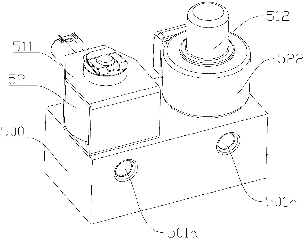
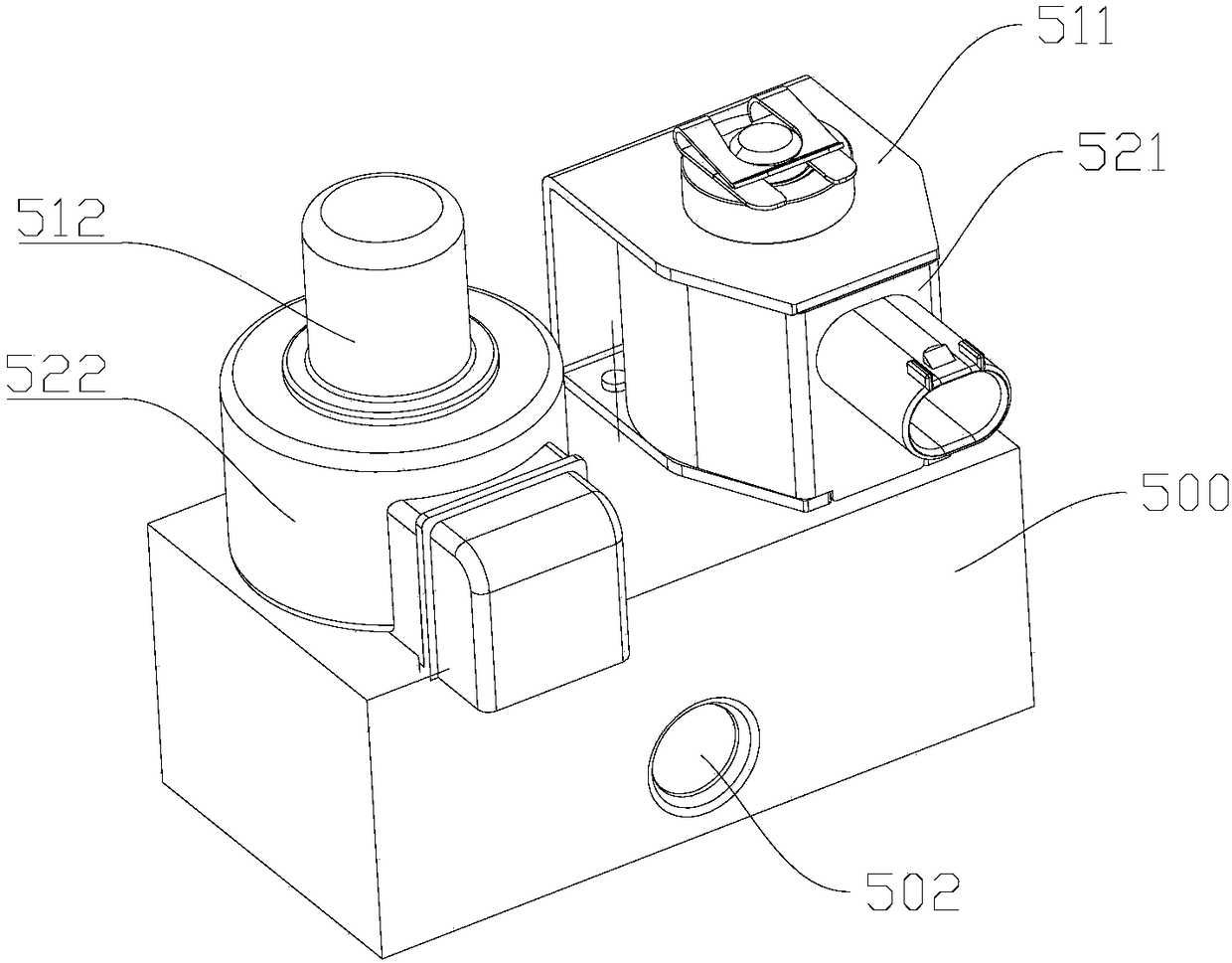
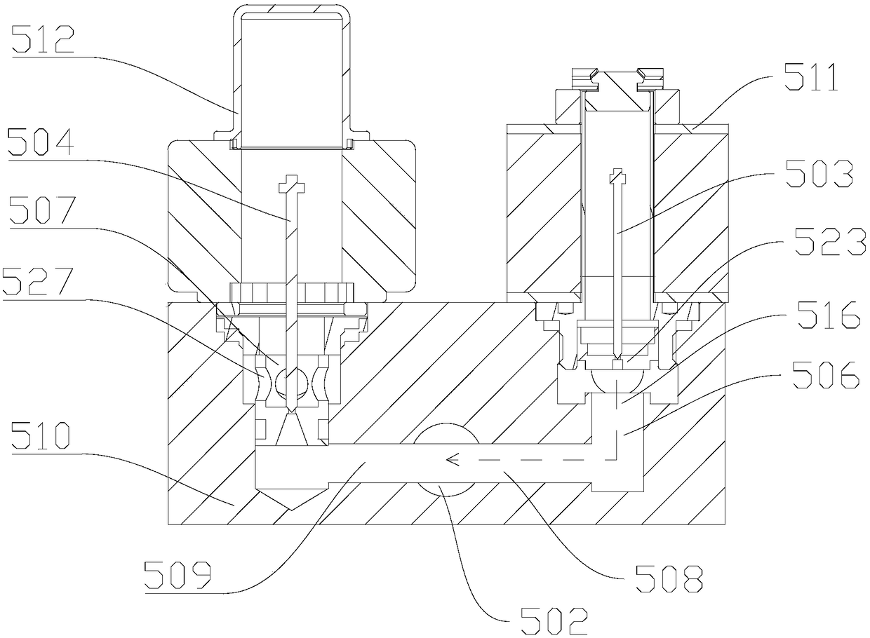
[0037] Such as Figure 1 to Figure 6 As shown, the present disclosure provides an expansion switching valve, including a valve body 500, ...


PUM


Abstract

The invention provides an expansion switch valve. The expansion switch valve comprises a valve body (500), wherein an inlet (501), an outlet (502) and an inner flow passage communicating between the inlet and the outlet are formed in the valve body (500), a first valve element (503) and a second valve element (504) which are parallel to each other are installed on the inner flow passage, and the first valve element (503) enables the inlet and the outlet to directly communicate or be disconnected; and the second valve element (504) enables the inlet and the outlet to communicate or be disconnected through a throttling hole (505). In this way, the first valve element and the second valve element are integrally installed on the inner flow passage of the same valve body, so that the on-off control function or the throttling expansion control function of a refrigerant can be realized, the structure is simple, and the production and the installation are easy. When the expansion switch valveis applied to a heat pump system, the pipeline connection can be simplified, the cost can be reduced, the refrigerant filling amount of the whole heat pump system is reduced, and the oil return of a compressor is facilitated.

Description

technical field [0001] The present disclosure relates to the field of control valves, in particular, to an expansion switch valve. Background technique [0002] In the heat pump system, it is sometimes necessary to control the throttling and depressurization of the refrigerant or only pass through without throttling, but the existing electronic expansion valve can only control the refrigerant throttling or not. In order to meet this requirement of the heat pump system, the prior art uses a structure in which an electronic expansion valve and an electromagnetic switch valve are connected in parallel. This structure requires two tee joints and six pipelines, and the structure is relatively complicated and inconvenient to install. When the solenoid valve is closed and the electronic expansion valve is used, the inlet of the electronic expansion valve is a medium-temperature and high-pressure liquid refrigerant, and the outlet of the electronic expansion valve is a low-temperat...

Claims


Application Information

Patent Timeline
Patent Type & Authority Applications(China)
IPC IPC(8): F16K11/22F16K1/00F16K1/38F16K1/42F16K31/06F25B41/06F25B41/325
CPCF16K1/00F16K1/385F16K1/42F16K11/22F16K31/0627F25B41/34F25B41/325F25B41/345F16K1/38F16K11/20F16K31/06Y02B30/70
Inventor 黄健张小伟陈雪峰叶梅娇
Owner BYD CO LTD
Why Eureka
Try Eureka