Transmission method of synchronous access signal block, network side equipment and user terminal

A network-side device and access signal technology, applied in the field of communication, can solve problems such as poor time synchronization accuracy

Active Publication Date: 2018-07-06
VIVO MOBILE COMM CO LTD
View PDF5 Cites 10 Cited by
  • Summary
  • Abstract
  • Description
  • Claims
  • Application Information

AI Technical Summary

Problems solved by technology

[0004] Embodiments of the present invention provide a method for transmitting synchronous access signal blocks, network-side equipment and user terminals, so as to solve the problem of relatively poor accuracy of time synchronization

Method used


Image

  • Transmission method of synchronous access signal block, network side equipment and user terminal
  • Transmission method of synchronous access signal block, network side equipment and user terminal
  • Transmission method of synchronous access signal block, network side equipment and user terminal

Examples


no. 1 example

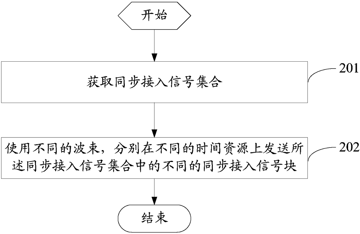
[0041] see figure 2 , figure 2 It is a flowchart of a method for transmitting a synchronous access signal block provided by an embodiment of the present invention, as shown in figure 2 shown, including the following steps:

[0042] Step 201, acquire a synchronous access signal set, the synchronous access signal set includes a plurality of synchronous access signal blocks, each synchronous access signal block includes PSS, SSS and PBCH signals, each PBCH signal includes MIB, the The MIB includes sequence number information, and the sequence number information is used to indicate the sequence number of the synchronization access signal block where the MIB is located in the synchronization access signal set.

[0043]In the embodiment of the present invention, the number of synchronous access signal blocks (SS blocks) included in the above-mentioned synchronous access signal set (SS burst) may be less than or equal to the number of subframes included in a frame, and may also ...

no. 2 example

[0054] see image 3 , image 3 is a flow chart of another method for transmitting a synchronous access signal block provided by an embodiment of the present invention, as shown in image 3 shown, including the following steps:

[0055] Step 301, generate a synchronous access signal set, the synchronous access signal set includes a plurality of synchronous access signal blocks, each synchronous access signal block includes PSS, SSS and PBCH signals, each PBCH signal includes MIB, the The MIB includes sequence number information, and the sequence number information is used to indicate the sequence number of the synchronization access signal block where the MIB is located in the synchronization access signal set.

[0056] Wherein, for the set of synchronous access signals, reference may be made to the corresponding description of the first embodiment, which will not be repeated here, and the same beneficial effect may be achieved.

[0057] It should be noted that, in step 301,...

no. 3 example

[0140] see Figure 10 , Figure 10 is a flow chart of another method for transmitting a synchronous access signal block provided by an embodiment of the present invention, as shown in Figure 10 shown, including the following steps:

[0141] Step 1001, search for different synchronous access signal blocks in the synchronous access signal set on different time resources, each synchronous access signal block in the synchronous access signal set includes PSS, SSS and PBCH signals, each Each PBCH signal includes a master information block MIB, and the MIB includes sequence number information, and the sequence number information is used to indicate the sequence number of the synchronization access signal block in which the MIB is located in the synchronization access signal set.

[0142] Wherein, step 1001 may be that the user terminal searches for different synchronous access signal blocks in multiple time resources, and when the PSS or SSS in the synchronous access signal block...


PUM


Abstract

The invention discloses a transmission method of a synchronous access signal block, network side equipment and a user terminal. The method comprises the following steps: acquiring a synchronous accesssignal set, wherein the synchronous access signal set comprises multiple synchronous access signal blocks, each synchronous access signal lock comprises PSS, SSS and PBCH signals, each PBCH signal comprises MIB, the MIB comprises serial number information, and the serial number information is used for representing a serial number of the synchronous access signal block located by the MIB in the synchronous access signal set; and respectively sending different synchronous access signal blocks in the synchronous access signal set on different time resources by using different wave beams. Therefore, the user terminal can perform the time synchronization by using the serial number information of the synchronous access signal. The time synchronization accuracy can be improved through the transmission method disclosed by the embodiment of the invention.

Description

technical field [0001] The present invention relates to the field of communication technology, in particular to a method for transmitting synchronous access signal blocks, network side equipment and user terminals. Background technique [0002] At present, the millimeter wave band (6-100GHz) has attracted much attention due to its advantages of rich spectrum resources and wide transmission bandwidth, and has become an essential technology for future communication system (eg 5G) standards. However, a prominent shortcoming of millimeter wave technology is that the path loss is very large, and, as the frequency increases, the path loss increases, which leads to a small coverage area of ​​the narrow beam of the millimeter wave band. [0003] In the existing communication system, the base station repeatedly sends the same synchronous access signal at different times using different beams, and different beams cover different areas, so as to realize the broadcast function and expan...

Claims


Application Information

Patent Timeline
Patent Type & Authority Applications(China)
IPC IPC(8): H04W48/10H04W48/16H04W56/00
CPCH04W48/10H04W48/16H04W56/00
Inventor 李建军
Owner VIVO MOBILE COMM CO LTD
Why Eureka
Try Eureka