Safe hydraulic control double-mode perforating machine

A dual-mode, punching machine technology, applied in metal processing, etc., can solve the problems of high price, low safety, and poor practicability, and achieve the effects of low manufacturing cost and maintenance cost, improved work efficiency, and reasonable design

Inactive Publication Date: 2018-07-10
广州常佰机械设计有限公司
View PDF6 Cites 0 Cited by
  • Summary
  • Abstract
  • Description
  • Claims
  • Application Information

AI Technical Summary

Problems solved by technology

[0002] At present, many kinds of punching machines in the prior art are drill bit punching machines. This kind of punching machine needs to punch holes one by one when the punching operation is required. Repeated positioning and clamping are required, the efficiency is low, and the punching quality is not high , not suitable for mass production in processing plants, or, although there are automatic hydraulic punching machines at present, their structure is complicated, the operation is cumbersome, the practicability is not strong, the safety is low, the price is expensive, and it can only meet a single punching mode needs, the operation is troublesome when replacing the punching head, and it cannot meet the existing needs

Method used


Image

  • Safe hydraulic control double-mode perforating machine
  • Safe hydraulic control double-mode perforating machine
  • Safe hydraulic control double-mode perforating machine

Examples


Embodiment Construction

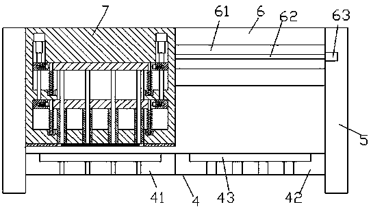
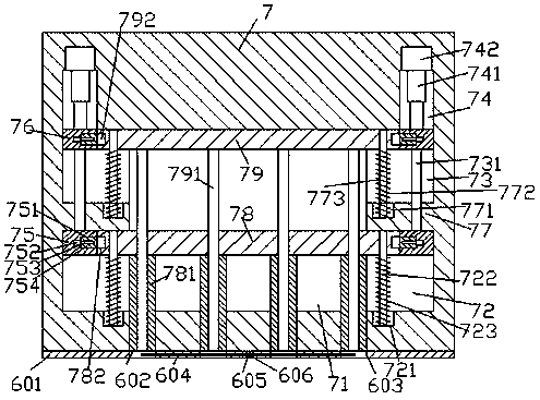
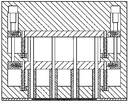
[0024] Such as Figure 1-Figure 7 As shown, a safe hydraulically controlled dual-mode punching machine of the present invention includes a frame and a punching device 7, and the inside of the punching device 7 is provided with a placement cavity 71, and the inner walls of the left and right sides of the placement cavity 71 The first sliding groove 73, the partition plate 77 and the second sliding groove 72 are symmetrically arranged in turn from top to bottom, and the first sliding rod 79 extending toward the left and right sides is arranged above the placement cavity 71, and the first sliding The extension ends on the left and right sides of the rod 79 respectively extend into the first sliding grooves 73 on the left and right sides and are connected by sliding fit. A second sliding rod 78 extending toward the left and right sides is provided below the placement cavity 71 . The extension ends on the left and right sides of the second sliding rod 78 respectively extend into th...


PUM


Abstract

The invention discloses a safe hydraulic control double-mode perforating machine. The safe hydraulic control double-mode perforating machine comprises a frame and a perforating device; the perforatingdevice is internally provided with a placing chamber; the inner walls of the left and right sides of the placing chamber are each sequentially symmetrically provided with a first sliding chute, a partition plate and a second sliding chute from top to bottom; a first sliding rod is arranged above the placing chamber in a manner of extending towards the left and right sides; the extending tail endsof the left and right sides of the first sliding rod correspondingly extend into the first sliding chutes positioned at the left and right sides and are connected with the first sliding chutes in a sliding fit manner; a second sliding rod is arranged below the placing chamber in a manner of extending towards the left and right sides; the extending tail ends of the left and right sides of the second sliding rod correspondingly extend into the second sliding chutes positioned at the left and right sides and are connected with the second sliding chutes in a sliding fit manner; the bottom of thesecond sliding rod is provided with a plurality of groups of punching sleeves which are arranged in a manner of extending downwards and penetrating through the end face of the bottom of the perforating device; and each punching sleeve is internally connected with a punching rod extending up and down in a sliding fit manner. The safe hydraulic control double-mode perforating machine disclosed by the invention is simple in structure, reasonable in design and convenient to operate, can realize automatic control on double-mode switching and perforation control, improves the work efficiency and islow in manufacturing cost and maintenance cost.

Description

technical field [0001] The invention relates to the field of processing machinery, in particular to a safe hydraulically controlled dual-mode punching machine. Background technique [0002] At present, many kinds of punching machines in the prior art are drill bit punching machines. This kind of punching machine needs to punch holes one by one when the punching operation is required. Repeated positioning and clamping are required, the efficiency is low, and the punching quality is not high , not suitable for mass production in processing plants, or, although there are automatic hydraulic punching machines at present, their structure is complicated, the operation is cumbersome, the practicability is not strong, the safety is low, the price is expensive, and it can only meet a single punching mode needs, the operation is troublesome when replacing the punching head, and the existing needs cannot be met. Contents of the invention [0003] The technical problem to be solved b...

Claims


Application Information

Patent Timeline
Patent Type & Authority Applications(China)
IPC IPC(8): B26F1/14B26F1/02B26D5/12B26D5/00B26D7/18
CPCB26D5/00B26D5/12B26D7/18B26F1/02B26F1/14
Inventor 范苏
Owner 广州常佰机械设计有限公司
Why Eureka
Try Eureka