
Coupling agent sealing and collecting device for control rod drive mechanism ultrasonic inspection

A driving mechanism, ultrasonic inspection technology, applied in the direction of material analysis, measurement device, instrument, etc. using sonic/ultrasonic/infrasonic waves, which can solve the problem of poor airbag sealing, inability to completely empty the couplant, and the connection between the airbag and the shell. Air leakage and other problems, to achieve the effect of easy coupling

Pending Publication Date: 2018-07-10
RES INST OF NUCLEAR POWER OPERATION +1
View PDF0 Cites 0 Cited by
  • Summary
  • Abstract
  • Description
  • Claims
  • Application Information

AI Technical Summary

Problems solved by technology

[0003] At present, for the ultrasonic inspection of the sealed weld seam that controls the one-rod drive mechanism, the airbag is used to tightly seal the seal. However, after the airbag is inflated, due to the expansion and contraction of the airbag, there is an air leakage problem at the connection between the airbag and the shell, which in turn makes the airbag The seal is not tight and the couplant slowly flows out; at the same time, after the inspection is completed, because the couplant cannot be completely emptied, when the airbag is released to disassemble the equipment, part of the couplant will flow down the outer wall of the control rod drive mechanism ; so corresponding design is needed to solve the above problems

Method used


Image

  • Coupling agent sealing and collecting device for control rod drive mechanism ultrasonic inspection
  • Coupling agent sealing and collecting device for control rod drive mechanism ultrasonic inspection
  • Coupling agent sealing and collecting device for control rod drive mechanism ultrasonic inspection

Examples


Embodiment Construction

[0025] The present invention will be further described below in conjunction with the accompanying drawings and embodiments.

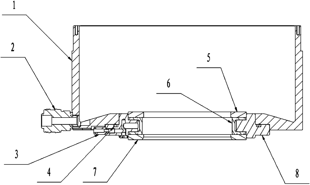
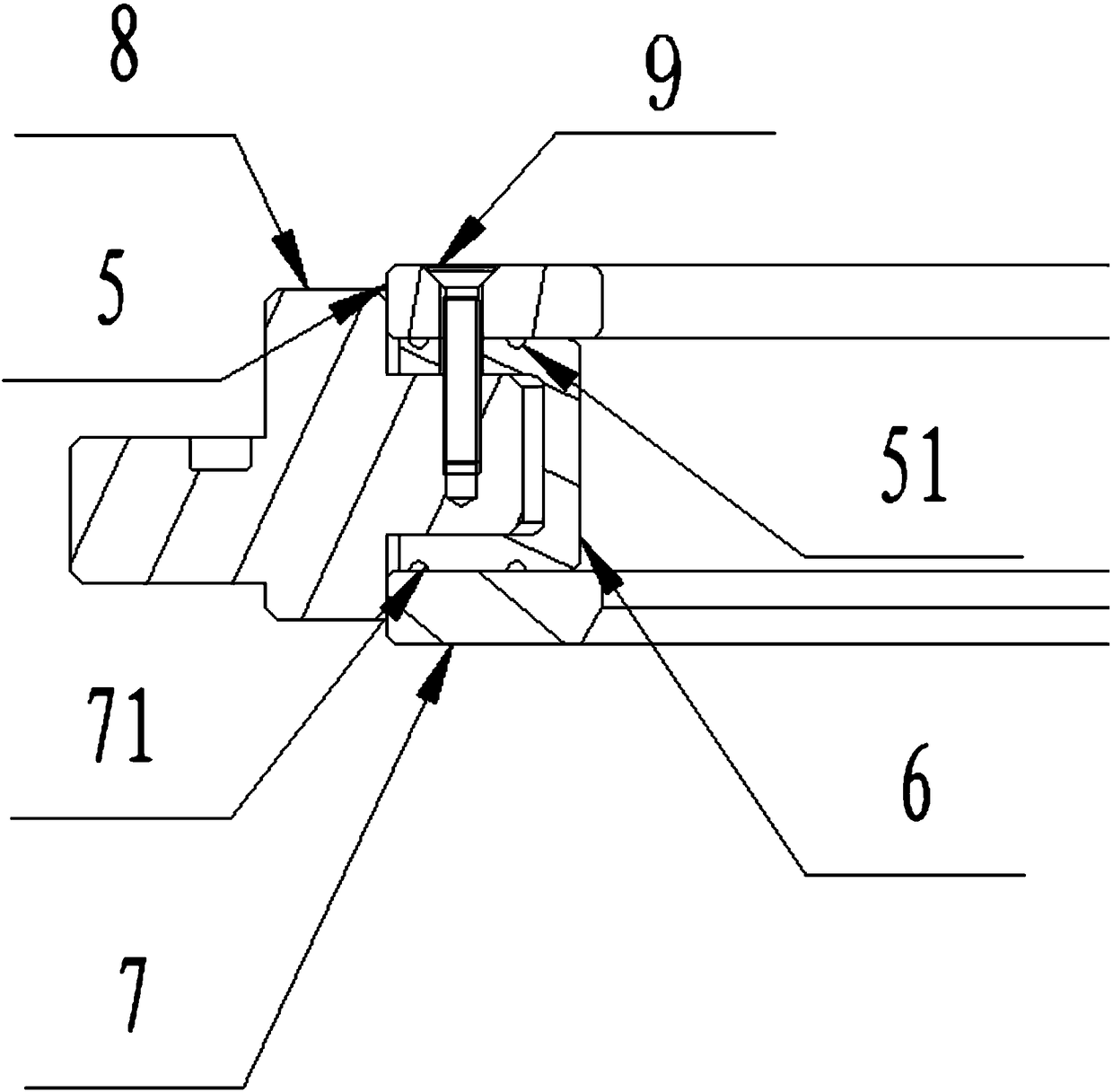
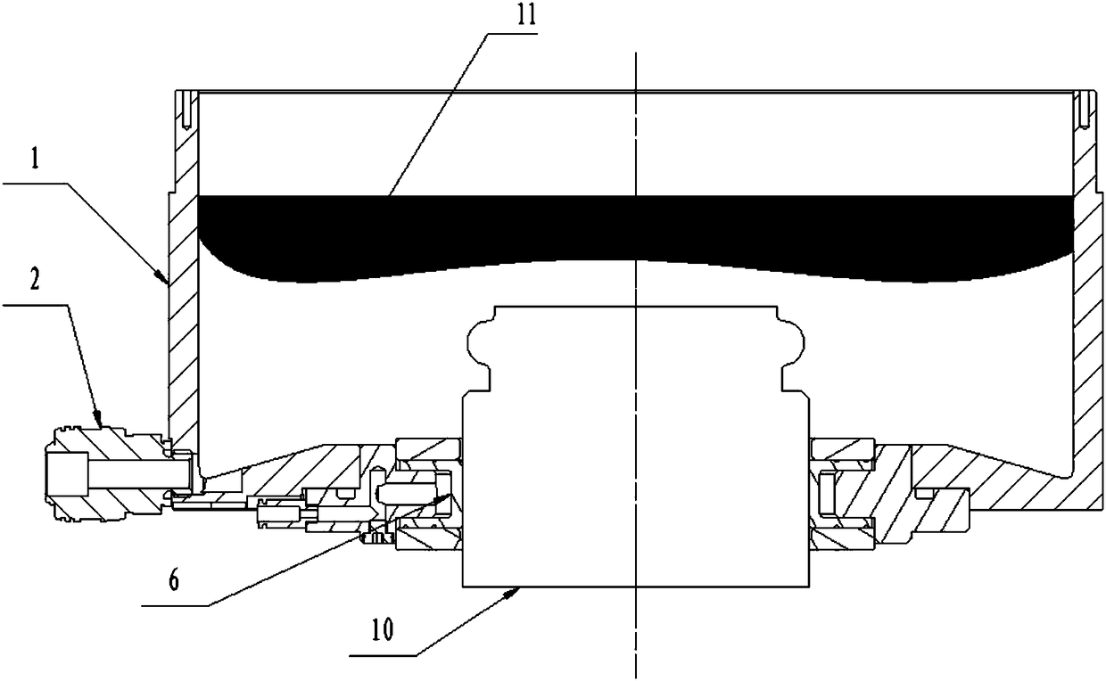
[0026] Such as figure 1 , figure 2 As shown, the present invention is a couplant seal collection device for ultrasonic inspection of the control rod drive mechanism, including a housing 1, a couplant inlet and outlet joint 2, an airbag inflation joint 3, an O-ring 4, and an airbag upper pressure plate 5 , airbag 6, airbag lower pressure plate 7, airbag connecting block 8, airbag screw 9.

[0027] The housing 1 is a hollow cylindrical structure as a whole, including side walls and a bottom with a through hole in the center. The bottom is designed as a special geometric shape, and the upper surface is slope-shaped with a high middle and low surroundings, which is beneficial for the coupling agent 11 to flow from a high place to a low place under the action of gravity; Form a sealed connection.

[0028] The bottom of the side wall of the shell 1 is pr...


PUM


Abstract

The invention discloses a coupling agent sealing and collecting device for control rod drive mechanism ultrasonic inspection and relates to sealing and collecting devices. The coupling agent sealing and collecting device is characterized in that the bottom of a shell is of a slope shape, and a coupling agent flows from a high position to low positions around; a coupling agent inlet connector is mounted at the bottom of the lateral wall of the shell; an air bag connecting block is fixedly mounted at the bottom of the shell, and the shell, an O-shaped sealing ring, the air bag connecting block compress to form a static sealing structure; an air bag is mounted on the inner side of the air bag connecting block, and an air bag upper compression plate, the air bag and an air bag lower compression plate are compressed to the air bag connecting block through air bag screws; an air bag inflation connector is mounted on the air bag connecting block and used for inflating the air bag; when the air bag is inflated, the air bag and a control rod drive mechanism form locking and sealing. When the coupling agent sealing and collecting device mounted on the outer wall of the control rod drive mechanism works, the coupling agent can be effectively sealed and collected to guarantee the coupling effect of an ultrasonic probe, and influence of the coupling agent on the electric components of a power station is avoided at the same time.

Description

technical field [0001] The invention relates to a liquid seal collection device, in particular to a coupling agent seal collection device for ultrasonic inspection of a control rod drive mechanism. Background technique [0002] There are a lot of equipment in nuclear power plants, and the forms of welds are also different; the control rod drive mechanism is an important part of the primary circuit, and there are many special-shaped sealing ring welds on it, which need to be aged through regular ultrasonic inspection manage. The inspection of the sealing weld of the control rod drive mechanism is carried out from the installation of the equipment on the outer wall. The ultrasonic probe needs to be immersed in the couplant, so it is necessary to effectively seal the couplant during the inspection, and effectively seal the couplant after the inspection is completed. Otherwise, the couplant will flow down the outer wall of the control rod drive mechanism and damage the electric...

Claims


Application Information

Patent Timeline
IPC IPC(8): G01N29/22G01N29/28
CPCG01N29/22G01N29/28
Inventor 胡啸丁冬平成照宇侯居斌李瑞霞周礼峰乐磊
Owner RES INST OF NUCLEAR POWER OPERATION
Learn More