Optical switch structure

An optical switch and incident fiber technology, applied in the field of communication, can solve the problems of increasing the optical switch coupling loss, unable to exceed 64 channels, and fiber breakage, etc., and achieve the effect of reducing the coupling loss

Pending Publication Date: 2021-01-05
深圳市欧亿光电技术有限公司
View PDF0 Cites 0 Cited by
  • Summary
  • Abstract
  • Description
  • Claims
  • Application Information

AI Technical Summary

Problems solved by technology

[0004] 1. The two-dimensional optical fiber array adopts the interspersed packaging method, which is easy to break the optical fiber, and it uses a corroded optical fiber with a smaller cladding diameter, which is easier to break
[0005] 2. The interspersed packaging form of the two-dimensional optical fiber array is prone to rotation of the optical fiber, and it is difficult to achieve the same direction packaging of the array optical fiber, which will increase the coupling loss of the optical switch and cannot be used to make a polarization-maintaining optical switch.
[0006] 3. The number of channels cannot be too many, and generally cannot exceed 64 channels
[0007] The above problems have greatly affected the production efficiency and cost of high-channel optical switches, and limited the further promotion of the optical switch market.

Method used


Image

  • Optical switch structure
  • Optical switch structure

Examples


Embodiment Construction

[0022] The following will clearly and completely describe the technical solutions in the embodiments of the present invention with reference to the accompanying drawings in the embodiments of the present invention. Obviously, the described embodiments are only some, not all, embodiments of the present invention.

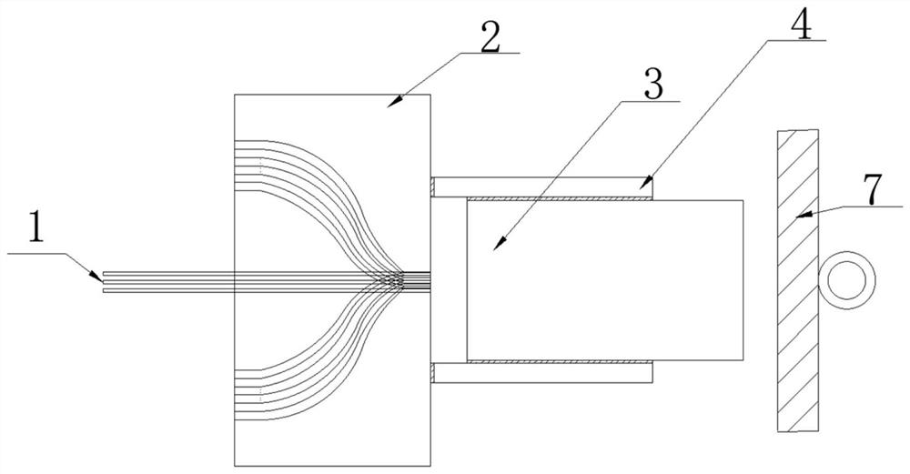
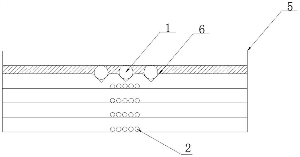
[0023] refer to Figure 1-Figure 2 , an optical switch structure, including an incident optical fiber array 1, a multilayer waveguide array 2, a lens 3, a glass tube 4, a cover plate 5, a V-shaped groove 6 and a MEMS rotating mirror 7, and the V-shaped groove 6 is located in the multilayer waveguide array 2 On the top of one layer, the incident fiber array 1 is arranged in the V-shaped groove 6, the cover plate 5 is set above the incident fiber array 1, the glass tube 4 is set on the right side of the multilayer waveguide array 2, and the lens 3 is set In the glass tube 4, the MEMS rotating mirror 7 is arranged on the side of the lens 3 away from the multilayer waveg...


PUM


Abstract

The invention discloses an optical switch structure and relates to the communication technology field, and the structure comprises an incident optical fiber array, a multilayer waveguide array, a lens, a glass circular tube, a cover plate, a V-shaped groove and an MEMS rotating mirror, wherein the V-shaped groove is located at the top of one layer of the multilayer waveguide array, the incident optical fibers are arranged in the V-shaped groove, and the cover plate is arranged above the incident optical fibers; and the glass circular tube is arranged on the right side of the multilayer waveguide array. The invention provides an optical switch structure which integrates an incident optical fiber array and a multi-layer waveguide array, enables densely-spaced channels to be fanned out into sparse intervals through optical waveguides, facilitates the coupling connection with an output optical fiber array, and can achieve the great increase of the number of light-emitting channels, so as to solve the problem that in the prior art, the number is small due to the fact that the diameter size of optical fibers and the angle of a rotating mirror are limited and lens differences exist.

Description

technical field [0001] The present invention relates to the technical field of communication, and more specifically, relates to an optical switch structure. Background technique [0002] In recent years, IP-based Internet services have shown explosive growth. This growth trend has not only changed the relationship between the IP network layer and the underlying transmission network, but also brought new challenges to the networking mode, node design, management and control of the entire network. requirements. An intelligent network architecture - automatic switching optical network has become a hotspot in current system research. Its core node is composed of optical cross-connect equipment. Through OXC, it can realize dynamic wavelength routing and flexible and effective management of optical network. OXC technology is one of the key technologies in the increasingly complex DWDM network, and the optical switch, as a functional device for switching optical paths, is a key pa...

Claims


Application Information

Patent Timeline
IPC IPC(8): G02B6/35
CPCG02B6/3518G02B6/3546
Inventor 高阳王森
Owner 深圳市欧亿光电技术有限公司
Why Eureka
Try Eureka