
Cooling water tank for imaging device

A technology for cooling water tanks and imaging equipment, which can be used in the fields of radiological diagnostic instruments, medical science, and diagnosis, and can solve the problem of limited installation space for cooling systems

Pending Publication Date: 2018-07-13
RAYSOLUTION DIGITAL MEDICAL IMAGING CO LTD
View PDF0 Cites 4 Cited by
  • Summary
  • Abstract
  • Description
  • Claims
  • Application Information

AI Technical Summary

Problems solved by technology

In the existing PET / CT equipment, the PET equipment and the CT equipment form a series connection in space, and the mechanical structures that make up the two imaging systems are closely combined in the working state, and there are strict requirements on the relative positional relationship between the two. The installation space for the cooling system is very limited, so how to set up the cooling system so that it can fully realize the cooling of the PET equipment in the limited installation space is one of the important issues related to the performance of the PET equipment

Method used


Image

  • Cooling water tank for imaging device
  • Cooling water tank for imaging device
  • Cooling water tank for imaging device

Examples


Embodiment Construction

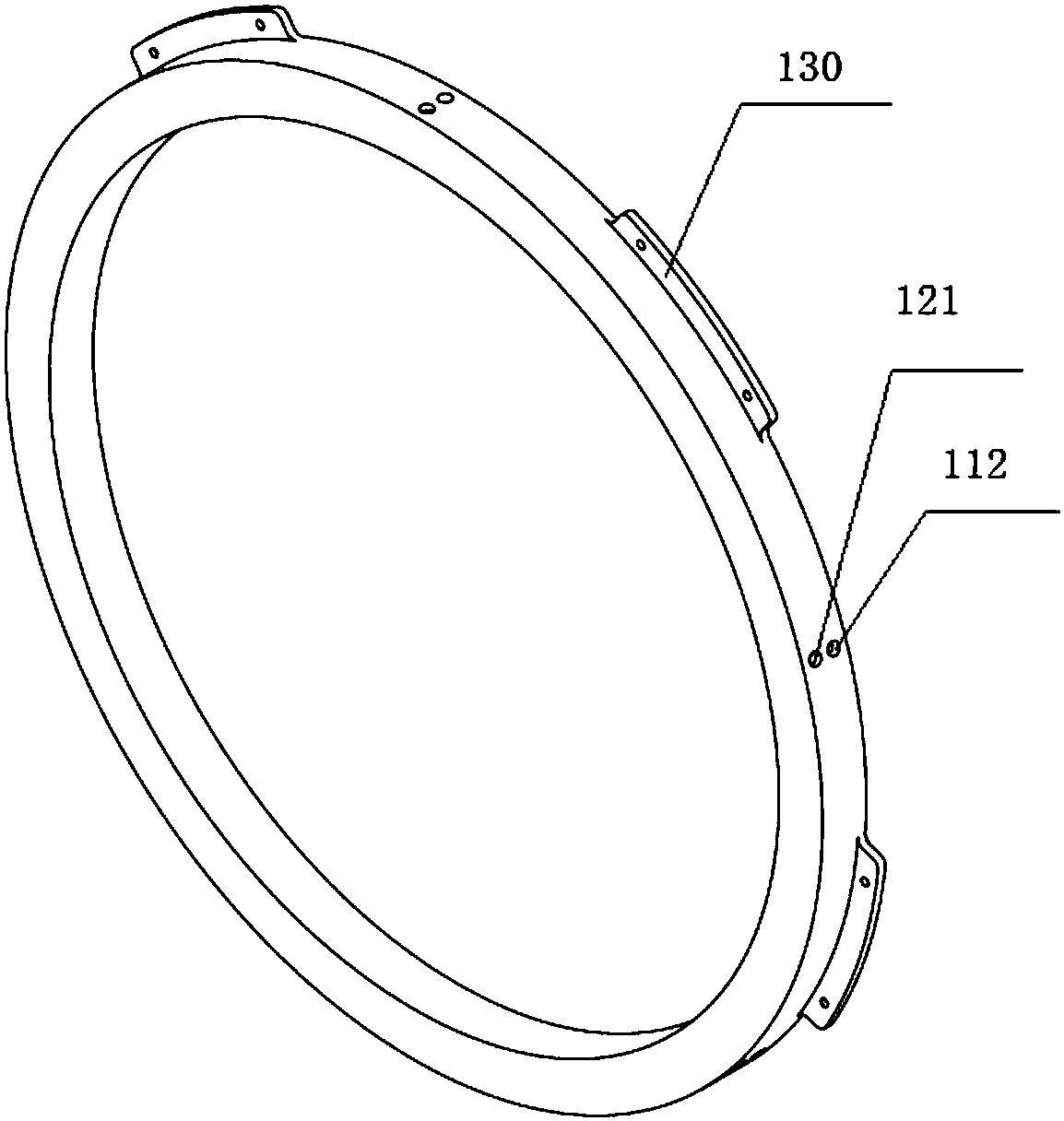
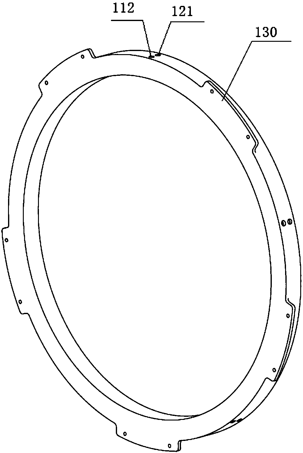
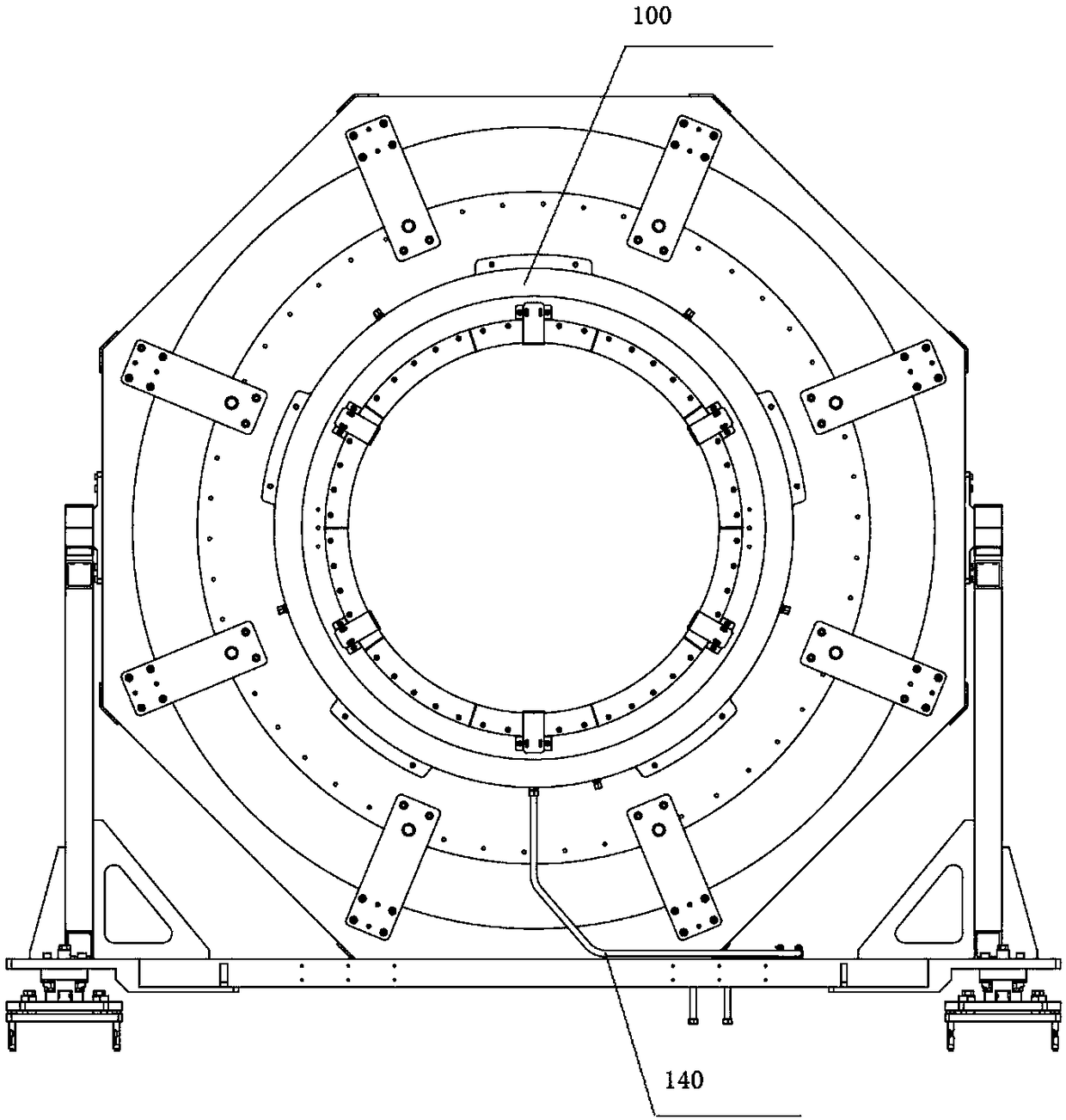
[0032] like figure 1 and figure 2 As shown, the present invention discloses a cooling water tank 100 for an imaging device, which is used for cooling the detector module in the PET system, and includes a liquid inlet chamber and a liquid outlet chamber connected to each other, the liquid inlet chamber and the liquid inlet chamber are both An annular structure, the inner diameter of both of which is not smaller than the aperture of the scanning channel of the imaging device; wherein the liquid inlet chamber includes a liquid inlet chamber 110, at least one set of first-type liquid inlet ports 111 and at least one liquid inlet chamber arranged on the liquid inlet chamber A set of first-type liquid outlets 112, the first-type liquid inlet 111 is in communication with the outside for the introduction of cooling liquid; The second type of liquid inlet 121 and at least one group of second type of liquid outlet 122, the second type of liquid outlet 122 communicates with the outside...


PUM


Abstract

Provided is a cooling water tank for an imaging device. The device is used for cooling detector modules in a PET system, and comprises a liquid inlet chamber and a liquid outlet chamber which are communicated with each other, wherein the liquid inlet chamber and the liquid outlet chamber are both annular structures, and the inner diameters of the liquid inlet chamber and liquid outlet chamber areboth no less than the bore diameter of a scanning channel of the imaging device; the liquid inlet chamber comprises a liquid inlet cavity, at least one set of first-type liquid inlet ports, and at least one set of first-type liquid outlet ports, the first-type liquid inlet ports and the first-type liquid outlet ports are formed in the liquid inlet cavity, and the first-type liquid inlet ports arecommunicated with the outside and used for introducing cooling liquid; the liquid outlet chamber comprises a liquid outlet cavity, at least one set of second-type liquid inlet ports, and at least oneset of second-type liquid outlet ports, the second-type liquid inlet ports and the second-type liquid outlet ports are formed in the liquid outlet cavity, and the second-type liquid outlet ports are communicated with the outside and used for discharging the cooling liquid; the first-type liquid outlet ports and the second-type liquid inlet ports are respectively communicated with all the detectormodules, the cooling liquid in the liquid inlet cavity flows through all the detector modules through the first-type liquid outlet ports, and flows into the liquid outlet cavity through the second-type liquid outlet ports. The cooling water tank for the imaging device has the advantages that the heat dissipation of the detector modules is effectively achieved, and at the same time, the installation space is reduced.

Description

technical field [0001] The invention relates to the technical field of medical equipment, in particular to a cooling system for PET imaging equipment. Background technique [0002] In modern nuclear medicine, PET equipment (Positron Emission Computed Tomography, Positron Emission Computed Tomography) is a relatively advanced clinical examination imaging equipment, which is usually used in combination with other medical imaging equipment, such as PET equipment and CT The combination of equipment (Computed Tomography) forms PET / CT equipment, and the combination of PET equipment and MR equipment (Magnetic Resonance, magnetic resonance scanning) forms PET / MR equipment. Taking PET / CT as an example, it is a new type of imaging equipment that organically combines two advanced imaging technologies: PET (functional metabolic imaging) and CT (anatomical structure imaging). It injects a small amount of positron nuclide tracers into the human body, and then uses special in vitro detect...

Claims


Application Information

Patent Timeline
IPC IPC(8): A61B6/03
CPCA61B6/032A61B6/037A61B6/4488
Inventor 张建兵
Owner RAYSOLUTION DIGITAL MEDICAL IMAGING CO LTD
Learn More