use co 2 Low-temperature impact labor pain equipment with rapid cooling

A technology of rapid cooling and low temperature shock, which is applied in the fields of heating appliances for treatment, cooling appliances for treatment, contraceptives, etc. It can solve the problems of difficult equipment maintenance and low service life of gas nozzles, and achieve the degree of equipment automation. High, long service life, low cost of product use

Active Publication Date: 2020-12-01
河南煜博医疗器械制造有限公司
View PDF19 Cites 0 Cited by
  • Summary
  • Abstract
  • Description
  • Claims
  • Application Information

AI Technical Summary

Problems solved by technology

[0006] The purpose of the present invention is to solve the problem of low service life of the gas nozzle of the low-temperature shock pain equipment using CO2 rapid cooling in the prior art, and the difficulty of maintenance in the later stage of the equipment

Method used


Image

  • use co  <sub>2</sub> Low-temperature impact labor pain equipment with rapid cooling
  • use co  <sub>2</sub> Low-temperature impact labor pain equipment with rapid cooling
  • use co  <sub>2</sub> Low-temperature impact labor pain equipment with rapid cooling

Examples


Embodiment 1

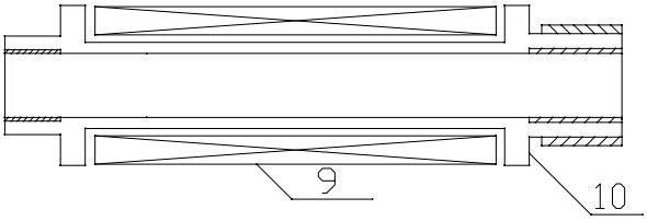
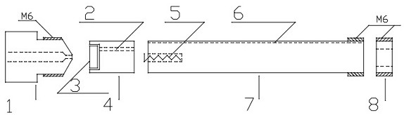
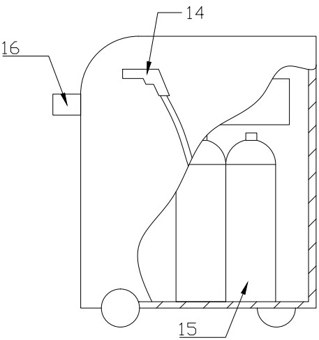
[0031] A low-temperature impact labor pain device that uses CO2 to rapidly cool down, see Figure 1 to Figure 4 , The carbon dioxide cylinder is set in the instrument shell, its outlet is connected to the jet pipe, the other end of the jet pipe is installed with a spray head, and the spray head is installed in the spray gun; the controller is installed in the instrument shell, and the controller is installed on the instrument shell. The connected touch LCD panel; the spray head is a rotary valve body 10, the valve body 10 is covered with an electromagnetic coil connected to the power supply element circuit, and the valve body 10 is coaxially equipped with an adjustment rod 7 and a piston 4 in turn. And the vaporization refrigeration cabin 1, the outer diameter of the adjustment rod 7 and the piston 4 is smaller than the inner hole diameter of the spray head to form a carbon dioxide liquid flow channel, one end of the spring 5 is connected to the adjustment rod, and the other en...


PUM


Abstract

The invention relates to the field of medical equipment, in particular to a low-temperature compact twinge equipment utilizing CO2 rapid cooling. The equipment is characterized in that a carbon dioxide steel cylinder is arranged inside an instrument shell, an outlet is connected with a gas injector pipe, an injector head is installed at the other end of the gas injector pipe, and the injector headis installed inside a spraying gun; a controller is installed inside the instrument shell, and a touch type liquid crystal panel connected with the controller is installed on the instrument shell; the injector head is a revolved body shaped valve body, the valve body is sleeved with an electromagnetic coil which is in circuit connection with a power supply component, an adjusting rod, a piston and an evaporation refrigeration cabin are sequentially and coaxially installed inside the valve body, the outer diameter of the piston and the outer diameter of the adjusting rod are smaller than the diameter of an inner hole of the injector head to form a carbon dioxide flow channel, one end of a spring is connected with the adjusting rod, the piston is installed at the other end so that the spring can drive the piston to move to control the flow channel to be opened and closed, and a liquid flow guiding groove is formed in the adjusting rod. The equipment has the advantages that the local lowtemperature impact position is convenient to control, percutaneous surface cooling speed is high, the automatic degree of the equipment is high, the service life of an impact head is long, and the product using cost is low.

Description

technical field [0001] The invention relates to the field of low-temperature impact pain equipment, in particular to a 2 Low-temperature impact labor pain equipment with rapid cooling. Background technique [0002] The general treatment method of low-temperature shock pain equipment includes the following steps: 1. Induce three to five low-temperature shock effects on the injury (subject to the formation of a thin layer of hoarfrost on the skin); 2. Spray on the surrounding swelling 3. Spray along the direction of the adjacent lymphatic reflux; generally, the treatment is performed from the distal end to the proximal end. [0003] In the specific work process, the injection time of each part of the patient should be within 30s of the low temperature impact time of the lesion (lesion area), within 15s of the low temperature impact time of the swelling around the injury, and within 15s of the low temperature impact time of the adjacent lymphatic reflux. The total treatment t...

Claims


Application Information

Patent Timeline
Patent Type & Authority Patents(China)
IPC IPC(8): A61M35/00A61F7/00
CPCA61F7/0053A61F7/0085A61F2007/0064A61F2007/0095A61M35/00
Inventor 蔡西国贺提金陈磊陈青超
Owner 河南煜博医疗器械制造有限公司
Why Eureka
Try Eureka