Petroleum pipeline trenching device

A technology for oil pipelines and sliding rods, which is applied in the directions of pipeline laying and maintenance, transportation and packaging, pipes/pipe joints/pipe fittings, etc. It can solve the problems of easy to catch foreign objects on the seabed, unable to drag and move, and large amount of trenching operations. , to achieve the effect of lowering traction power requirements, reducing traction and dragging costs, and reducing fuel consumption

Inactive Publication Date: 2018-07-13
吴申龙
View PDF6 Cites 2 Cited by
  • Summary
  • Abstract
  • Description
  • Claims
  • Application Information

AI Technical Summary

Problems solved by technology

[0003] Generally, in areas where high-speed ocean currents will cause displacement of pipelines, areas where pipelines are gradually damaged due to scouring, and areas where sailing ships break down and fishing operations may damage pipelines, it is often necessary to trench the laid pipelines in advance. This method Mainly use dredgers or furrow plows, and tugboats are generally used to open furrows. It is more suitable for hard soil than dredgers. When using these two methods to open trenches, pipe laying operations can be carried out at the same time , the backfilling of the ditch is sometimes completed by the natural movement of the seabed mud and sand, but this method requires a lot of ditching work, and the furrowing plow generally has a heavy weight, which is easy to catch foreign objects on the seabed, making it impossible to drag and move. The pipeline can only be laid up after the completion of the pipeline. The pipeline accurately falls into the trench opened on the seabed. The construction process of the immersed tube is required to be accurate and the operation is difficult. Therefore, we need a new type of trenching device to solve these problems.

Method used


Image

  • Petroleum pipeline trenching device
  • Petroleum pipeline trenching device
  • Petroleum pipeline trenching device

Examples


Embodiment Construction

[0021] The following will clearly and completely describe the technical solutions in the embodiments of the present invention with reference to the accompanying drawings in the embodiments of the present invention. Obviously, the described embodiments are only some, not all, embodiments of the present invention. Based on the embodiments of the present invention, all other embodiments obtained by persons of ordinary skill in the art without making creative efforts belong to the protection scope of the present invention.

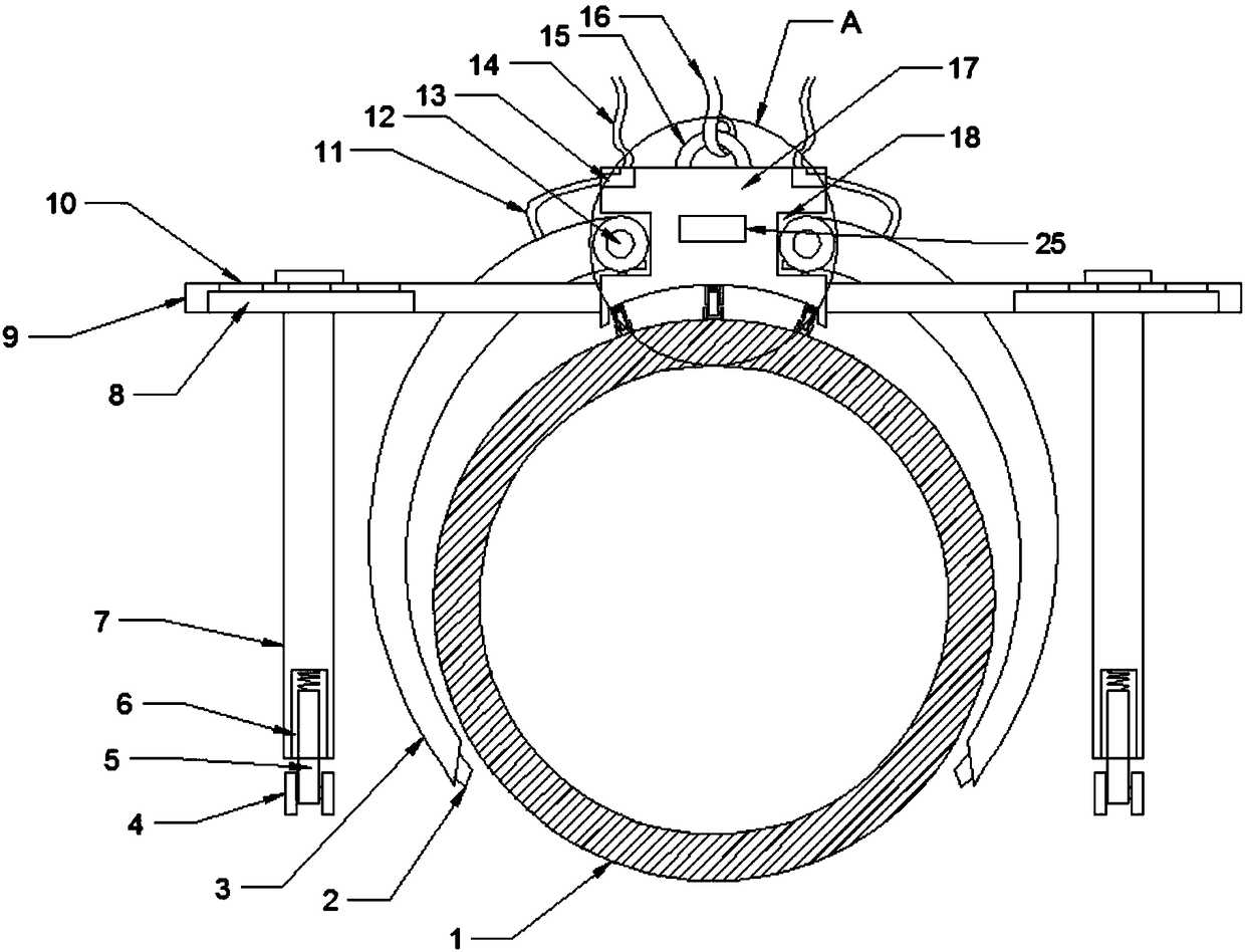
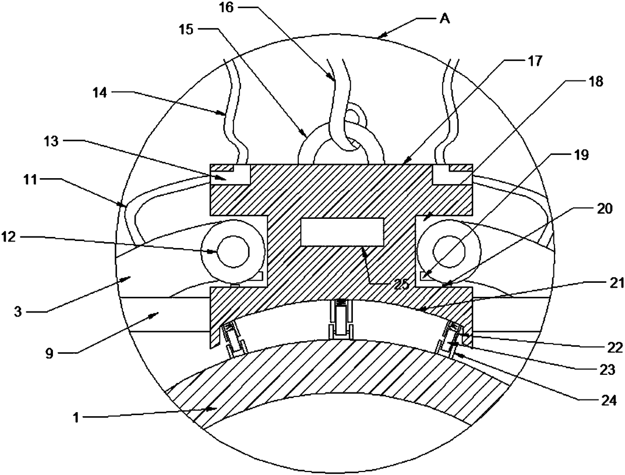
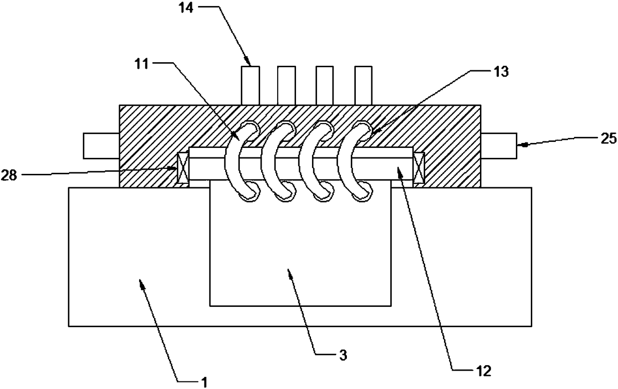
[0022] see Figure 1~5 , in an embodiment of the present invention, an oil pipeline ditching device includes an oil pipeline 1, an air nozzle 2, an air guide plate 3, a supporting wheel 4, a supporting telescopic rod 5, a supporting telescopic groove 6, a supporting sliding rod 7, and a sliding rod Groove 8, suspension rod 9, fixing bolt hole 10, transfer pipe 11, rotating shaft 12, transfer hole 13, air pipe 14, lifting ring 15, lifting rope 16, sliding base ...


PUM


Abstract

The invention discloses a petroleum pipeline trenching device. The petroleum pipeline trenching device comprises a petroleum pipeline, a sliding base is arranged at the top of the petroleum pipeline,the bottom of the sliding base is supported on the top surface of the petroleum pipeline through sliding wheels, and two suspension rods are fixed to the front position and rear position of the bottomof each of two side walls of the sliding base. Supporting sliding rods are fixed to the bottoms of the suspension rods, two sides of the bottom of each supporting telescopic rod are rotationally connected with supporting wheels, a gas guide plate is arranged between the two suspension rods on each side, and the top of each gas guide plate is fixed to the shaft wall of a rotating shaft. Each rotating shaft is rotationally fixed to the inner wall of a rotating shaft groove through a rotating shaft bearing, gas sprayers are arranged at the tail end of each gas guide plate, transfer pipes penetrate through transfer holes and are connected with gas delivery pipes, a lifting pull ring on the top of the sliding base is connected with a lifting rope, and a traction rope is connected to traction pull rings on a front panel and a rear panel of the sliding base. Through the sliding base buckled on the petroleum pipeline, a pipe trench is accurately formed in the position where a pipe is located,and thus the earthwork volume of excavation is reduced.

Description

technical field [0001] The invention relates to the field of oil pipeline construction equipment, in particular to an oil pipeline ditching device. Background technique [0002] In the process of offshore oil exploitation, the crude oil produced in the shallow sea can be directly loaded into the oil tanker from the production platform, but for the crude oil produced in the deep sea, the berthing of a large oil tanker on the production platform will threaten the safety of the platform. Single-point mooring of oil tankers, in this way, there must be oil pipelines connecting each production platform and single-point mooring, and laying oil and natural gas pipelines on the seabed, which also includes offshore positioning, laying pipelines and ditching etc. work. [0003] Generally, in areas where high-speed ocean currents will cause displacement of pipelines, areas where pipelines are gradually damaged due to scouring, and areas where sailing ships break down and fishing operat...

Claims


Application Information

Patent Timeline
Patent Type & Authority Applications(China)
IPC IPC(8): F16L1/16B66C1/42B66C13/08
CPCF16L1/16B66C1/42B66C13/08
Inventor 吴申龙
Owner 吴申龙
Why Eureka
Try Eureka