Rocker switch

A rocker switch and rocker technology, which is applied to the parts of flip switches/rocker switches, etc., can solve the problems of switch damage and arc generation, and achieve the effect of stable electrical contact and reliable cooperation.

Active Publication Date: 2018-07-13
NINGBO BULL ELECTRIC CO LTD
View PDF11 Cites 4 Cited by
  • Summary
  • Abstract
  • Description
  • Claims
  • Application Information

AI Technical Summary

Problems solved by technology

[0004] The invention provides a rocker switch, which aims to solve the problem in the prior art that when the user presses the switch, the rocker and the support will repeatedly contact and separate, thereby generating arcs and ablation of surrounding components, resulting in damage to the switch

Method used


Image

  • Rocker switch
  • Rocker switch
  • Rocker switch

Examples


Embodiment 1

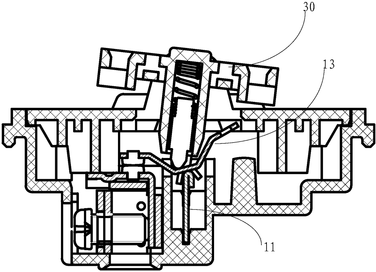
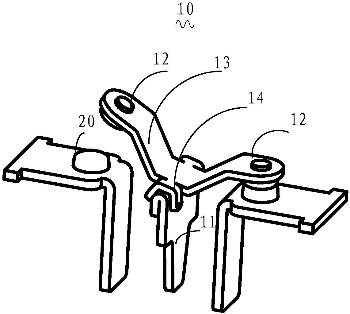
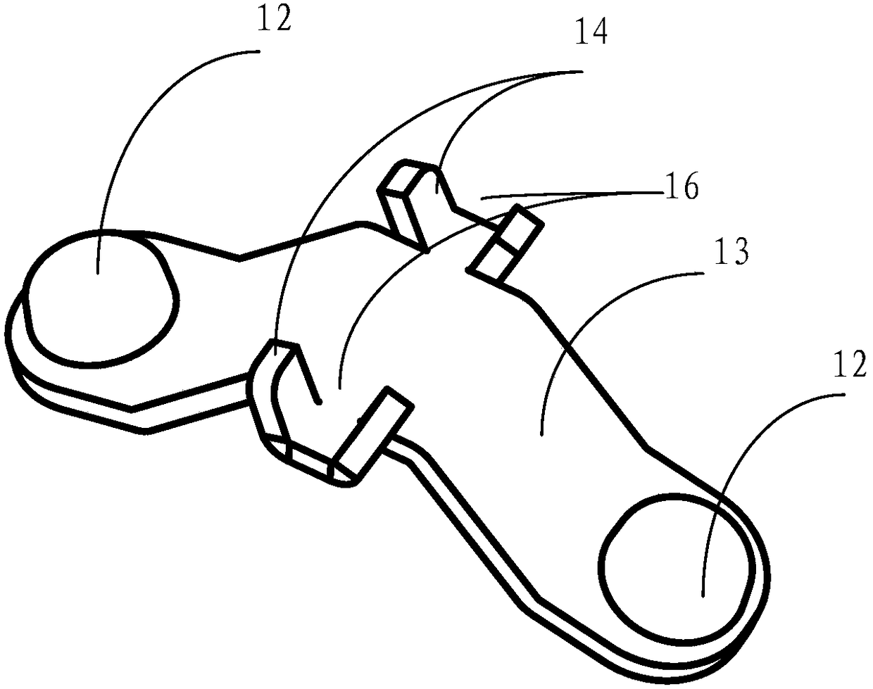
[0029] Such as figure 1 It is an overall structural diagram of a rocker switch provided by an embodiment of the present invention, figure 2 It is a rocker switch 10 provided by an embodiment of the present invention, including a support member 11 and a rocker assembly, wherein the rocker assembly includes contacts 12 , a rocker body 13 and a clamping portion 14 on the rocker body 13 . image 3 and Figure 4 respectively figure 2 Partial enlarged view, specifically, image 3 show figure 2 The specific structure of the rocker assembly, Figure 4 show figure 2 The specific structure of the support.

[0030] In the embodiment of the present invention, such as figure 2 The user presses the seesaw main body 13 so that the contacts 12 on the seesaw main body 13 are in contact with or disconnected from the terminal 20 according to the direction of the user's force, so as to control the conduction and disconnection of the switch.

[0031] Wherein, a clamping part 14 is pro...

Embodiment 2

[0035] The embodiment of the present invention provides a seesaw switch 10. Specifically, the difference from the first embodiment is that the above-mentioned clamping part 14 is located on the contact surface between the seesaw main body 13 and the support member 11, or is located on both sides of the seesaw main body. side; in an optimized embodiment of the present invention, when the clamping part 14 is located on both sides of the seesaw main body 13, in order to balance the force, the seesaw assembly is more stable when the user presses the switch 30, and the clamping part 14 is set as They are symmetrically distributed on both sides of the seesaw main body 13 .

[0036] In one embodiment of the present invention, the seesaw switch 10 is a dual-control switch, and contacts 12 are provided at both ends of the seesaw main body 13. Generally, in order to ensure uniform force, the clamping part 14 is arranged on the middle of the plate assembly.

[0037] In one embodiment of...


PUM


Abstract

The invention is applicable to the field of electric appliances and provides a rocker switch. The rocker switch comprises a support part and a rocker component in contact fit with the support part andis characterized in that the rocker component comprises a contact, a rocker body and a clamp part located on the rocker body; the clamp part is coordinated with the support end of the support part toprevent discontinuous contact caused by the displacement of the rocker component on the support part when the rocker switch is switched on or switched off. The rocker switch has the advantages that the clamp part is coordinated with the support end of the support part, so that the rocker plate can be firmly coordinated with the support part, electric contact stability is achieved, and discontinuous contact, caused by the displacement of the rocker component on the support part when a user presses the switch, between the rocker plate and the support part is avoided.

Description

technical field [0001] The invention belongs to the field of electrical appliances, in particular to a rocker switch. Background technique [0002] Rocker switches are also called rocker switches, rocker switches, IO switches and power switches, and are widely used in water dispensers, treadmills, computer speakers, battery cars, motorcycles, ion TVs, power strips and other products. Generally, it mainly includes a base, a seesaw and a button assembly. The base is provided with a support for supporting the seesaw, and the seesaw can deflect around the support. When the button assembly is pressed, force can be indirectly applied to the seesaw to make it The deflection occurs, and then the contacts of the rocker are connected with the terminal components on the base, or separated from the terminal components on the base, so as to realize the conduction or disconnection of the rocker switch. [0003] In the prior art, the rocker switch generally moves laterally through the bon...

Claims


Application Information

Patent Timeline
Patent Type & Authority Applications(China)
IPC IPC(8): H01H23/16
CPCH01H23/16
Inventor 周定国
Owner NINGBO BULL ELECTRIC CO LTD
Why Eureka
Try Eureka