Tire skin and wheel hub separation equipment for generalized intelligent aircraft tire
What is Al technical title?
Al technical title is built by PatSnap Al team. It summarizes the technical point description of the patent document.
A technology for aircraft tires and separation equipment, which is applied in tire installation, tire parts, transportation and packaging, etc., which can solve the problems of increasing the labor intensity of maintenance personnel and difficult turning over, and achieve the effect of avoiding time-consuming and laborious, reasonable design and easy removal
Pending Publication Date: 2018-07-17
西安飞豹科技有限公司
View PDF0 Cites 3 Cited by
Summary
Abstract
Description
Claims
Application Information
AI Technical Summary
This helps you quickly interpret patents by identifying the three key elements:
Problems solved by technology
Method used
Benefits of technology
Problems solved by technology
[0003] When separating the tread from the hub, the hub is usually placed horizontally on the equipment, and the tread on the upper side of the tire is separated from the hub with a pressure plate or claw, and then the tire is turned over to the other side to separate the tread from the hub. On the one hand, because the wheel hub needs to be flipped to separate the tread on both sides from the wheel hub, the labor intensity of the maintenance personnel is increased. Especially for large aircraft, the weight of the tire exceeds 200kg, and it is more difficult for the maintenance personnel to turn over the tire. On the one hand, due to the different sizes of tires of different models, the airport needs to be equipped with equipment of the same form and different specifications to meet the needs of separating the tread from the hub
Method used
Image
Click on the blue label to locate the original text in one second.
Reading with bidirectional positioning of images and text.
Examples
Embodiment Construction
[0020] The following will clearly and completely describe the technical solutions in the embodiments of the present invention with reference to the accompanying drawings in the embodiments of the present invention. Obviously, the described embodiments are only some, not all, embodiments of the present invention. Based on the embodiments of the present invention, all other embodiments obtained by persons of ordinary skill in the art without making creative efforts belong to the protection scope of the present invention.
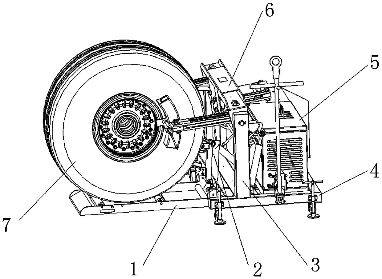
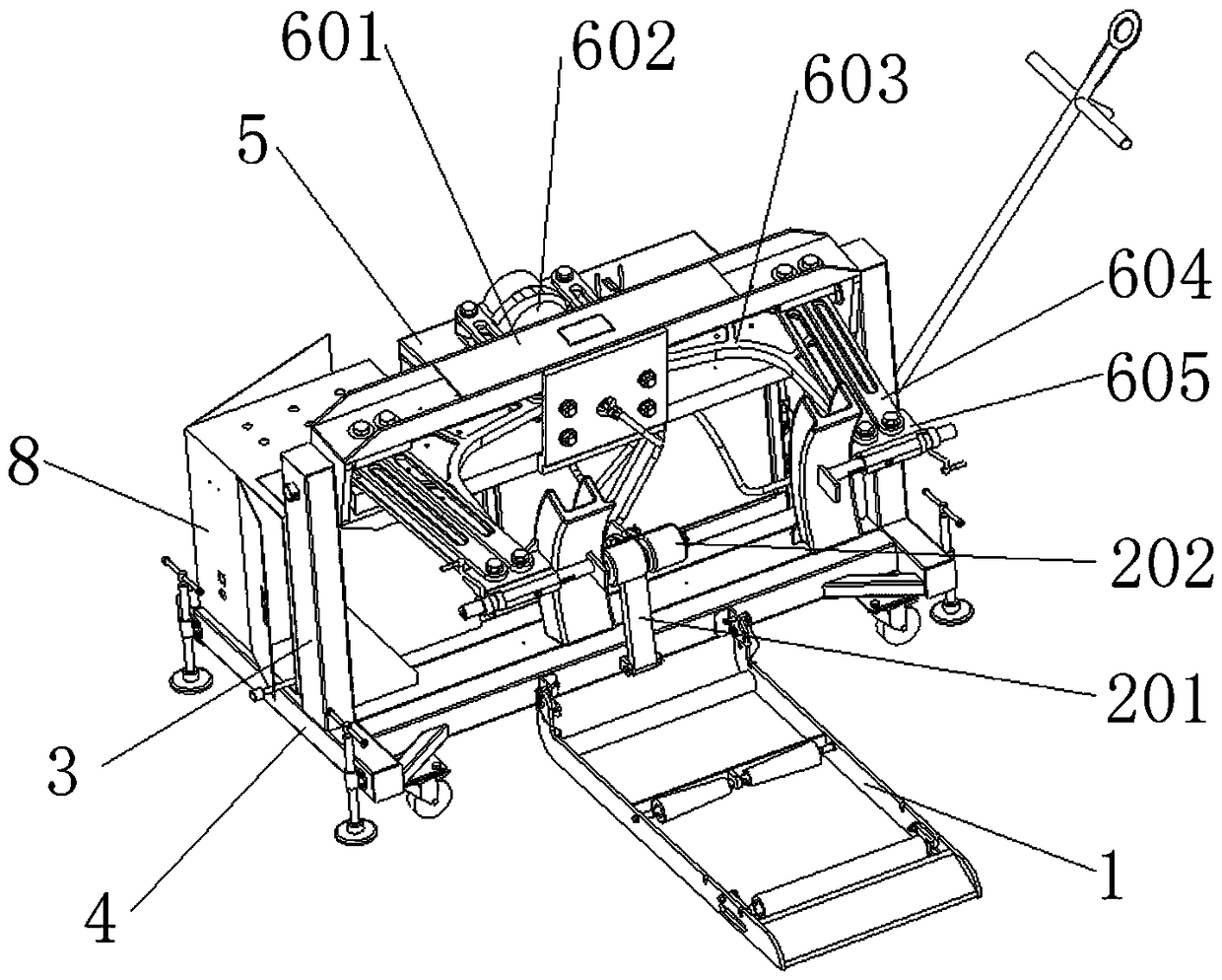
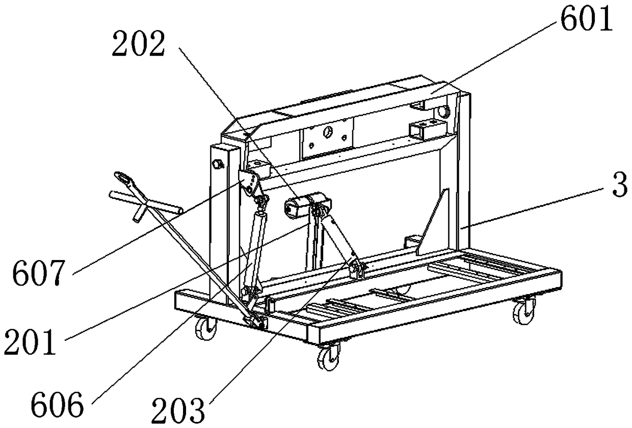
[0021] see Figure 1-5 As shown, a general intelligent aircraft tire skin and hub separation equipment includes a radial adjustment assembly 2 and a pitch adjustment assembly 6, one end of the rotating plate 201 of the radial adjustment assembly 2 is connected to the side surface of the carrier 4 The middle part is movably connected, and the top of one side surface of the rotating plate 201 is equipped with a backing wheel 202, and the top of the other side su...
PUM
Abstract
The invention discloses tire skin and wheel hub separation equipment for a generalized intelligent aircraft tire. The equipment comprises a lifting frame, a tapered roller, a long cylindrical roller,a radial adjustment assembly, a rotating plate, an abutting wheel, a first hydraulic push rod, a fixing plate, a bearing frame, a hydraulic oil controller, a pitching adjustment component, a rectangular frame, a cylindrical block, L-shaped plates, strip-shaped plates, square iron blocks, second hydraulic push rods, sector-shaped iron pieces, threaded rods, internal threaded tubes, sliding rods, push blocks, curved frames, a tire body and a power distribution box. The equipment is reasonable in design and has the function of adjusting the placement position of the tire, the tire surface and wheel hub separation various types of tires is achieved, and the situation is effectively avoided that the time and labor are wasted due to overturning of the tire; by prying the tire skin of the tire into the curved frames and adopting the second hydraulic push rods to drive the rectangular frame, the cylindrical block and the L-shaped plates to rotate downwards, the equipment helps to drive the curved frames to rotate downwards for a certain distance and keep stable, the effect of slightly pulling the tire skin of the tire by the curved frames is achieved, and the wheel hubs are conveniently taken out.
Description
technical field [0001] The invention relates to a tire skin and hub separating device, in particular to a general intelligent aircraft tire skin and hub separating device, belonging to the technical field of tire skin and hub separating equipment. Background technique [0002] Aircraft tires are mainly used to generate brake bonding force to stop the aircraft when landing, and at the same time support the weight of the aircraft when taxiing on the ground. During frequent replacement, it is necessary to use special tools to overcome the bonding force between the tread and the hub, so that the tires The face is separated from the hub. [0003] When separating the tread from the hub, the hub is usually placed horizontally on the equipment, and the tread on the upper side of the tire is separated from the hub with a pressure plate or claw, and then the tire is turned over to the other side to separate the tread from the hub. On the one hand, because the wheel hub needs to be fl...
Claims
Application Information
Patent Timeline
Application Date:The date an application was filed.
Publication Date:The date a patent or application was officially published.
First Publication Date:The earliest publication date of a patent with the same application number.
Issue Date:Publication date of the patent grant document.
PCT Entry Date:The Entry date of PCT National Phase.
Estimated Expiry Date:The statutory expiry date of a patent right according to the Patent Law, and it is the longest term of protection that the patent right can achieve without the termination of the patent right due to other reasons(Term extension factor has been taken into account ).
Invalid Date:Actual expiry date is based on effective date or publication date of legal transaction data of invalid patent.