Flushing device of low-water-tank toilet bowl

A technology for water tanks and toilets, applied in the field of sanitary ware, can solve problems such as insufficient water supply of cleaning water supply pipes, poor flushing effect, and inability to directly sense the water level of the water tank

Pending Publication Date: 2018-07-17
GUANGDONG HEGII SANITARY WARES CO LTD
View PDF10 Cites 3 Cited by
  • Summary
  • Abstract
  • Description
  • Claims
  • Application Information

AI Technical Summary

Problems solved by technology

[0003] In the prior art, the patent application with the Chinese Publication No. CN103104014A discloses a water supply conversion device for the lip and face of a low water tank toilet, which is realized by a brush ring ejector using the principle of negative pressure, and it is realized by setting a cleaning water supply pipe ( That is, the brush ring ejector), water supply conversion parts, water level adjustment parts, floats, floats, pipes and other components lead the flushing water from the water inlet valve to the lip of the toilet (that is, the brush ring) during the drainage process of the water tank. The pot surface is washed away, which solves the deficiency that the low water tank toilet in the prior art cannot meet the flushing requirements of the toilet pot surface
However, the technical solution disclosed in this patent application has the following disadvantages: when the water inlet valve enters the water, it will provide a suction force for the water inside the pipe body, and the water inside the pipe body is directly pumped to the toilet. Therefore, when working, the inside of the pipe body The water level is less affected by the water level of the water tank, but gr

Method used


Image

  • Flushing device of low-water-tank toilet bowl
  • Flushing device of low-water-tank toilet bowl
  • Flushing device of low-water-tank toilet bowl

Examples


Embodiment 1

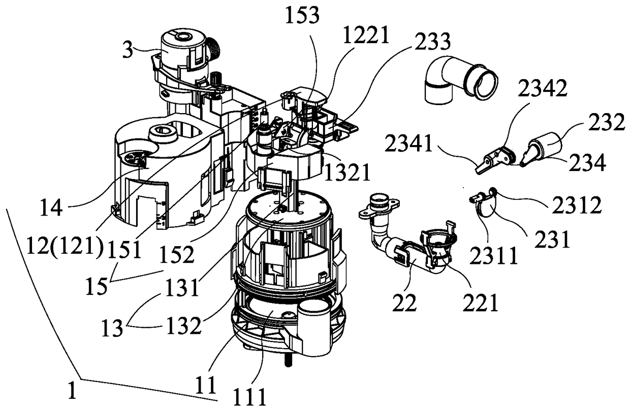
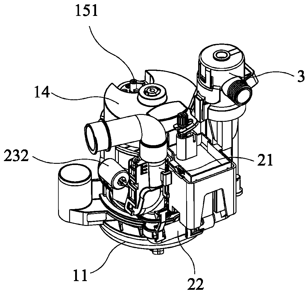
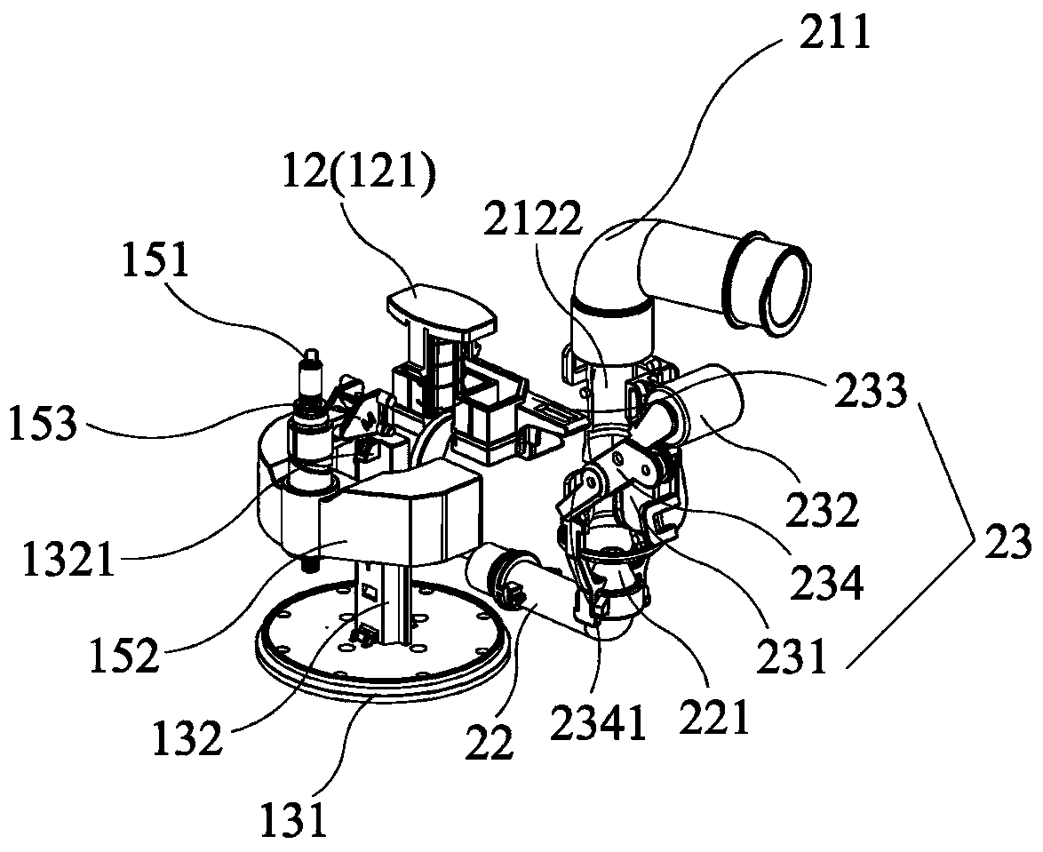
[0035] Such as Figure 1 to Figure 10 As shown, this embodiment discloses a flushing device for a low tank toilet, which is arranged in a water tank (not shown) of the toilet, and includes a drain valve 1 and a brush ring ejector 2; the drain valve 1 includes a The valve seat 11 of the drain port 111, the switch assembly 12, and the water stop assembly 13 controlled by the water level of the water tank and the switch assembly 12; the water stop assembly 13 actively blocks the drain port 111; the brush ring ejector 2 includes The brush ring pipe 21 communicated with the brush ring water channel (not shown) of the toilet, the spray pipe 22 communicated with the water inlet valve 3 of the toilet, and the switching mechanism 23 that controls the opening and closing of the brush ring pipe water circuit; the switching mechanism 23 includes Rotate to open and close the switching baffle 231 of the brush ring pipe 21 waterway, the switching float 232 used to drive the switching baffle ...

Embodiment 2

[0046] Cooperate Figure 11 to Figure 16 As shown, the difference between this embodiment and Embodiment 1 lies in the structure of the drain valve.

[0047] In this embodiment, specifically, the drain valve 1 is a clapper cover type drain valve, the water stop component 13 is a clapper cover 134 with an air chamber inside, and one end of the clapper cover 134 is hinged to the valve seat 11 , the hinge between the flap cover 134 and the valve seat 11 is connected to the limiting member 233; the switch assembly 12 is a lifting member 122 connected to the flap cover 134, and the lifting member 122 can be a chain or a pull rope.

[0048] Cooperate Figure 11 to Figure 16 As shown, the working process of the present invention in this embodiment will be described in detail below.

[0049] When the present invention was in the initial state, cooperate Figure 11 with Figure 12 As shown, the discharge port 111 of the drain valve 1 is blocked by the clapper cover 134, the drain v...


PUM


Abstract

The invention discloses a flushing device of a low-water-tank toilet bowl. The flushing device is arranged in a water tank of the toilet bowl, and comprises a drainage valve and a brush ring ejector,wherein the drainage valve comprises a valve seat, a switch component and a water stop component; the brush ring ejector comprises a brush ring pipe, an ejecting pipe and a switching mechanism for opening and closing a water path of the brush ring pipe; the switching mechanism comprises a switching baffle plate, a switching float and a limiting piece; the switching baffle plate is rotatably arranged in the brush ring pipe; the switching float gets linked with the switching baffle plate; and the limiting piece is linked with the water stop component. According to the flushing device provided bythe invention, the water path of the brush ring pipe is opened and closed under the control of the switching baffle plate, and the switching baffle plate is controlled by the switching float and thewater stop component while the switching float and the water stop component are controlled by a water level in the water tank, which is to say, the opening and closing of the water path of the brush ring pipe are actually controlled the water level of the water tank and are less associated to water intake pressure of a water intake valve; therefore, the water path of the brush ring pipe of the flushing device provided by the invention is more stable in opening and closing.

Description

technical field [0001] The invention relates to the field of sanitary ware, in particular to a flushing device for a low water tank toilet. Background technique [0002] Low tank toilets typically have the tank located at the rear of the toilet slightly lower than the toilet seat. When the position of the water tank sinks to the bottom of the water tank and is lower than the upper edge of the brush ring, the flushing of the pot surface of the toilet obviously cannot be realized by adopting the traditional gravity drainage method. The solution in the prior art is to use the brush ring ejector of the negative pressure principle to suck the water in the water tank to the brush ring with a higher level and then flow into the pot surface by means of the tap water inlet pressure, so as to realize the washing of the pot surface. [0003] In the prior art, the patent application with the Chinese Publication No. CN103104014A discloses a water supply conversion device for the lip and...

Claims


Application Information

Patent Timeline
IPC IPC(8): E03D1/36E03D1/32E03D1/35
CPCE03D1/32E03D1/35E03D1/36
Inventor 宋威
Owner GUANGDONG HEGII SANITARY WARES CO LTD
Why Eureka
Try Eureka