

Electric control selection valve and active bottle control distribution method using the valve
A valve selection, electronic control technology, applied in the valve operation/release device, valve details, valve device and other directions, can solve the problems of delaying the operation of the fighter, delaying the operation of the fighter, and difficulty in installation, so as to achieve smooth opening and reduce control. The effect of link and control simplification
- Summary
- Abstract
- Description
- Claims
- Application Information
AI Technical Summary
Problems solved by technology
Method used
Image

Examples
Embodiment Construction
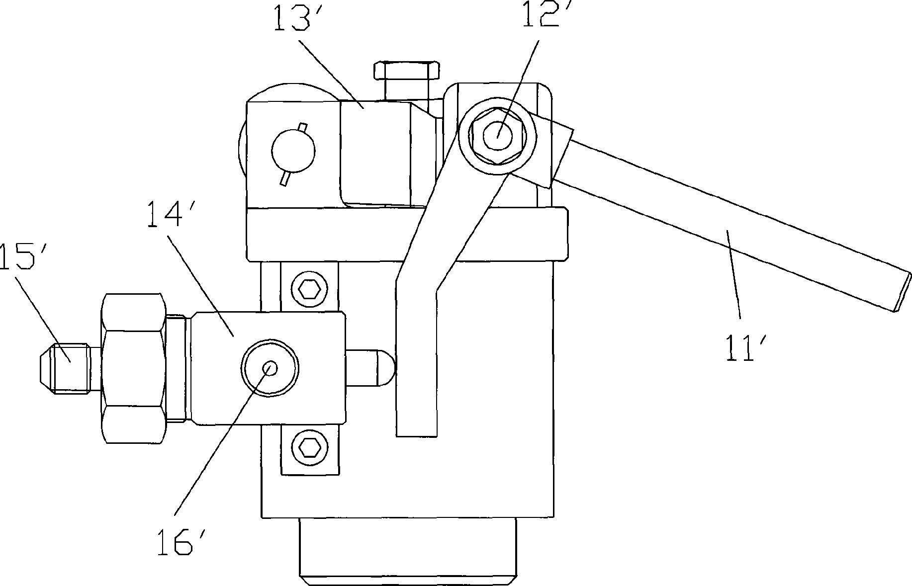
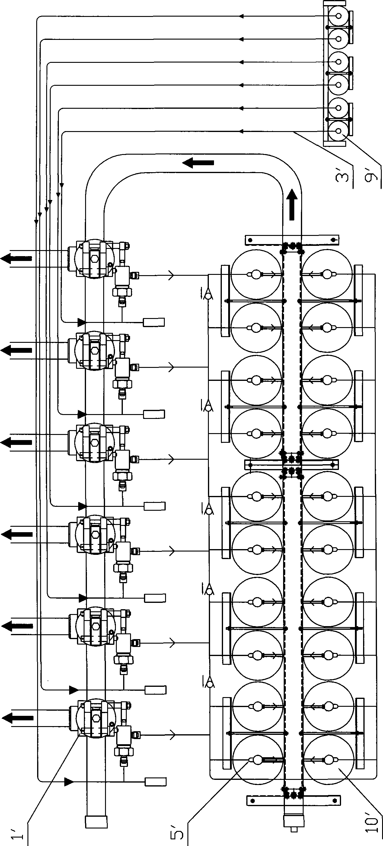
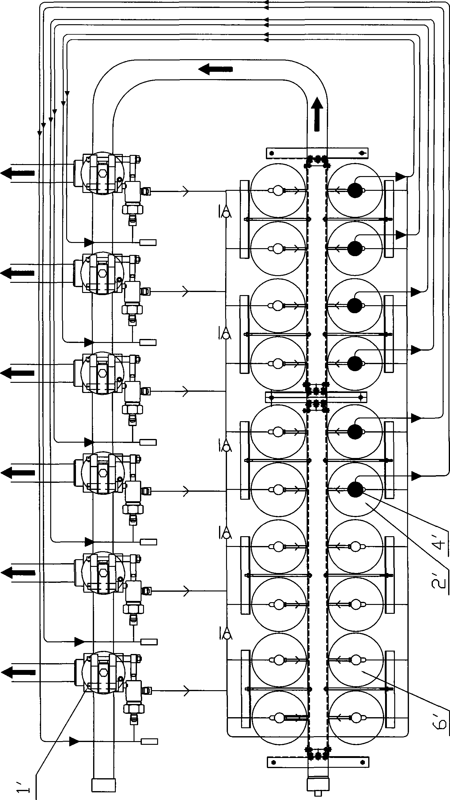
[0026] see Figure 4 and Figure 5 , is composed of the connection between the electric control drive device I and the selector valve II, the electric control drive device I is provided with a metal sealing diaphragm 1, and the metal sealing diaphragm 1 divides the electric control drive device I into an upper space I-1 and a lower space I-2, and the electric control driving device 1 is provided with a driving gas outlet 11. The selector valve II includes a valve body 2, a valve cover 3, a valve stem 4, a piston 7, a cylinder head 6 and a spring 8. The valve body 2 is provided with a total air inlet 13 and a total air outlet 12, a valve cover 3, a valve stem 4 , the piston 7, the cylinder head 6 and the spring 8 are located in the valve body 2, the spring 8, the piston 7, the cylinder head 6, and the valve cover 3 are sequentially set on the valve stem 4, and the valve cover 3 is located at the total air outlet 12, and the cylinder head 6 is fixed in the valve body 2, and th...
PUM
 Abstract
Description
Claims
Application Information