
Constant-torque electric EGR (Exhaust Gas Recirculation) valve driving mechanism

A technology of EGR valve and driving mechanism, applied in the direction of engine components, machines/engines, mechanical equipment, etc., can solve the problems of shortening the service life of the EGR valve, the inability of the center rod to move vertically, the axial offset of the rack, etc., and achieve the driving clearance. Reduce, ensure vertical motion, turn on stable effects

Inactive Publication Date: 2017-02-22
WUXI LONGSHENG TECH
View PDF6 Cites 0 Cited by
  • Summary
  • Abstract
  • Description
  • Claims
  • Application Information

AI Technical Summary

Problems solved by technology

However, the transmission of the gear and the rack will inevitably cause the axial deviation of the rack, which will cause the center rod to be unable to move vertically, which will cause the EGR valve to be stuck and shorten the service life of the EGR valve.

Method used


Image

  • Constant-torque electric EGR (Exhaust Gas Recirculation) valve driving mechanism
  • Constant-torque electric EGR (Exhaust Gas Recirculation) valve driving mechanism

Examples


Embodiment Construction

[0018] The present invention will be further described in detail below in conjunction with the accompanying drawings and specific embodiments.

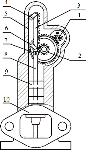
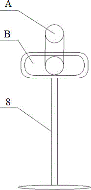
[0019] An electric EGR valve drive mechanism with constant torque, including a motor 1, a reduction mechanism, a drive mechanism and a guide mechanism arranged in the valve body 10, the output shaft of the motor drives the drive mechanism through the reduction mechanism, and further drives the center rod to move up and down, The guiding mechanism is arranged on the valve body and the driving mechanism, and is used to ensure that the driving mechanism can maintain linear motion in the vertical direction, and further ensure that the central rod can perform linear motion in the vertical direction.

[0020] In the present invention, the deceleration mechanism adopts the deceleration gear set 2, and the drive mechanism adopts a vertical drive rack 3, and the drive rack 3 and the motor 1 are meshed through the speed change gear set 2, and th...


PUM


Abstract

The invention discloses a constant-torque electric EGR (Exhaust Gas Recirculation) valve driving mechanism which comprises a motor arranged in a valve body, wherein the top end of a central rod in the valve body is hinged to a driving rack through a pin shaft; the driving rack is used for driving the central rod to move up and down and is engaged with the motor through a change gear set; and a guiding mechanism used for guiding the driving rack is arranged on the driving rack and located on the side opposite to saw teeth. By adopting a gear-rack driving combination, the constant-torque electric EGR valve driving mechanism greatly reduces a driving gap on the basis of guaranteeing reliable action of an EGR valve, ensures that a driving force arm remains unchanged when the EGR valve is opened to different degrees and the EGR valve is more stably opened and more accurately controlled, and can meet the operation requirements of the electric EGR valve of an engine with a large exhaust back pressure variation range.

Description

technical field [0001] The invention relates to the technical field of engine exhaust emission recirculation systems, in particular to a driving mechanism for an electric EGR valve. Background technique [0002] In the engine exhaust gas recirculation system (EGR system), the EGR valve is mainly used to adjust and control the flow of recirculated exhaust gas. The EGR valve adjusts the flow of exhaust gas by controlling the opening, so that the exhaust gas and fresh air are mixed in a certain proportion and then returned to the cylinder for recirculation. Recirculation to reduce the combustion temperature and combustion velocity in the cylinder to further reduce NO X emissions. [0003] At present, the driving mechanism of most EGR valves adopts the structure that the rocker arm and the slider cooperate. The rotation of the rocker arm drives the slider to move up and down, and further drives the center rod to move up and down, thereby driving the EGR valve to open and close...

Claims


Application Information

Patent Timeline
Patent Type & Authority Applications(China)
IPC IPC(8): F02M26/54
Inventor 于政王劲舒孙骋业
Owner WUXI LONGSHENG TECH
Learn More