

Chair
A chair and body technology, applied in the field of backrest mechanism, can solve the problems of inability to use, offset, increase the occupied area of the chair, etc., and achieve the effect of reducing the occupied area and improving the safety
- Summary
- Abstract
- Description
- Claims
- Application Information
AI Technical Summary
Problems solved by technology
Method used
Image

Examples
Embodiment 1
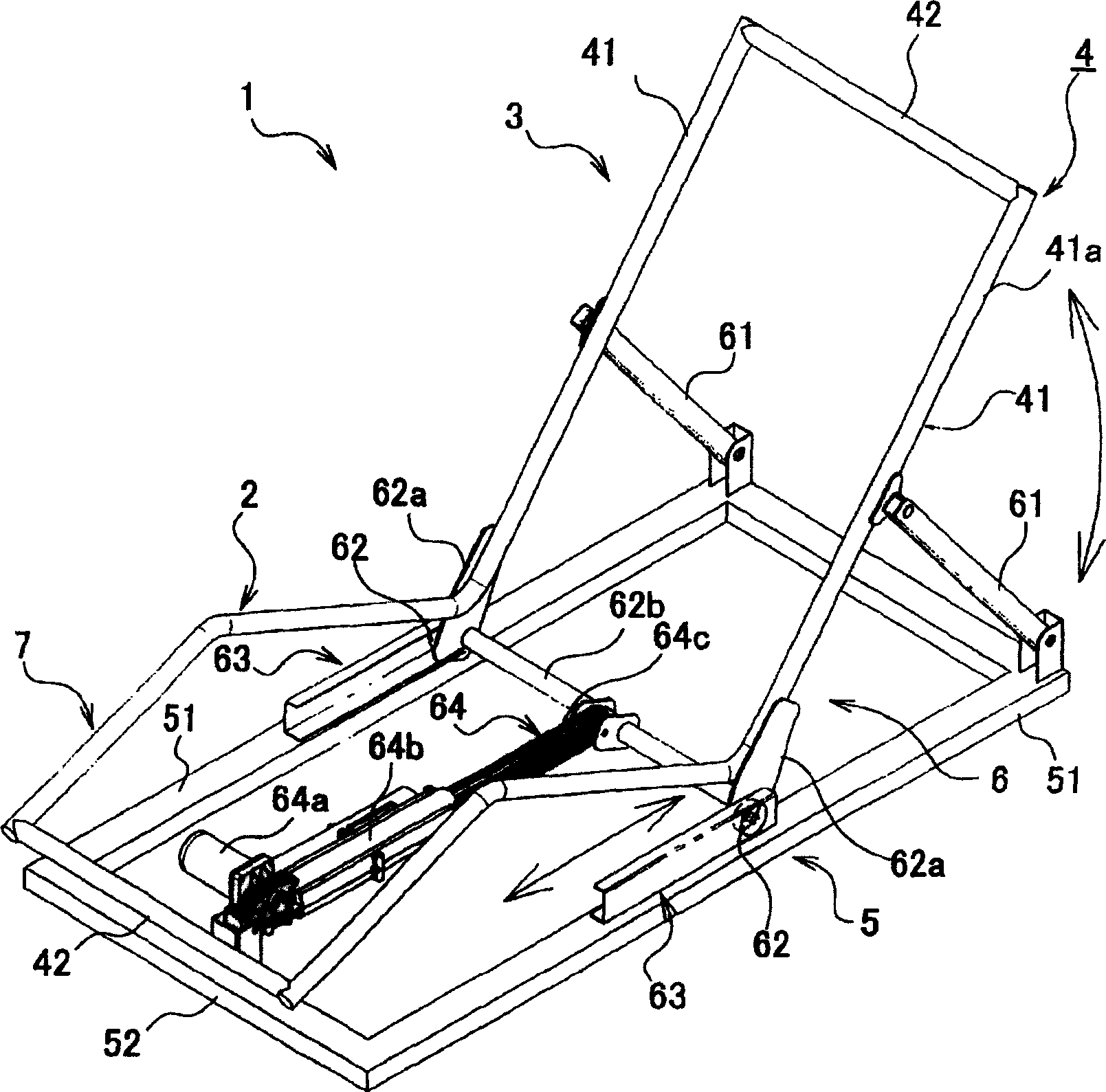
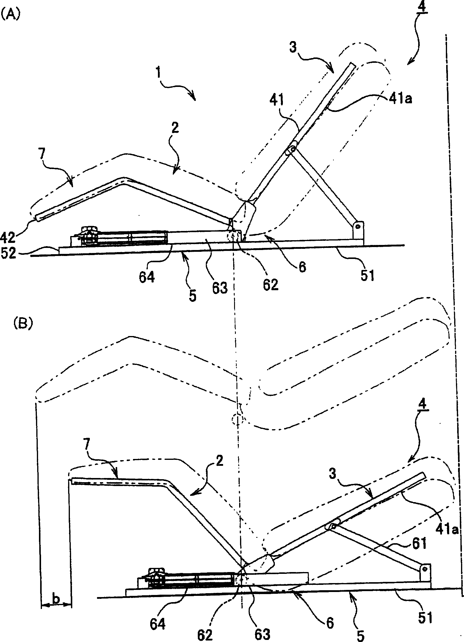
[0048] figure 1 and figure 2 It is the schematic diagram of the skeleton frame of the chair of the embodiment 1 of the present invention. 1 indicates the whole chair, which generally includes: a chair body 4 having a seat portion 2 and a back portion 3, a pedestal-shaped support portion 5 supporting the chair body 4, and a backrest mechanism 6 provided between the support portion 5 and the chair body 4. The backrest mechanism 6 can fold the backrest 3 backward and move the seat 2 and the backrest 3 forward while keeping the angles of the seat 2 and the backrest 3 constant.
[0049] In front of the seat part 2 of the chair body 4, a leg support part 7 is provided, and the back part 3, the seat part 2 and the leg support part 7 are integrally formed with a frame structure. That is, it has a pair of left and right vertical frames 41, 41 and a pair of front and rear horizontal frames 42, 42, and at the junction of the backrest 3 and the seat 2, the vertical frame 41 is bent int...
Embodiment 2
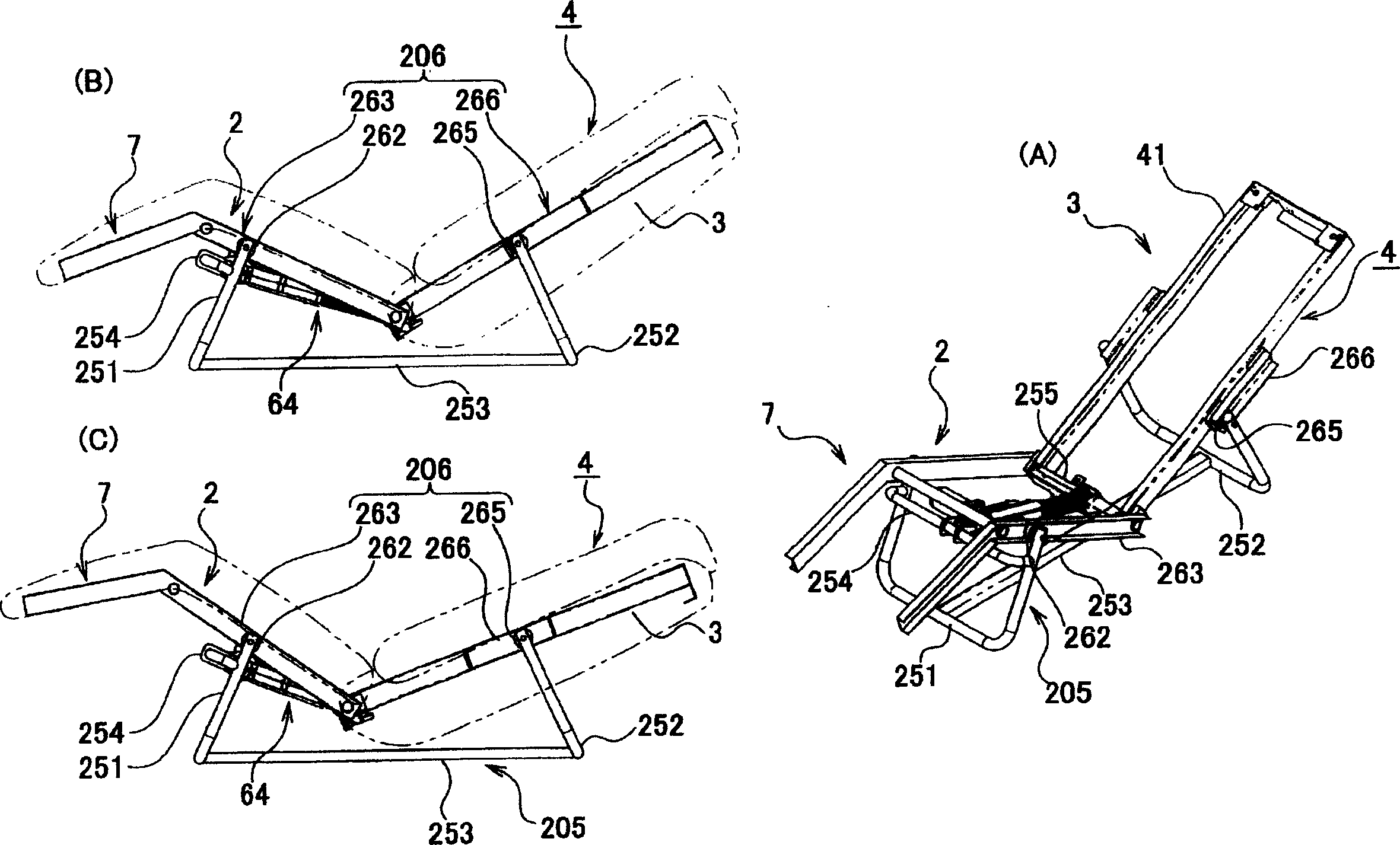
[0059] image 3 It is the schematic diagram of the chair of Embodiment 2 of the present invention. In the second embodiment, the support portion 205 is provided with a front support leg 251 and a rear support leg 252 separated from each other. The front support leg 251 and the rear support leg 252 are U-shaped members, and are integrally connected by a vertical frame 253 extending in the front-rear direction. In addition, the upper portions of the front support legs 251 are connected by a front frame 254 extending laterally.
[0060] The backrest mechanism 206 has: a front roller 262 as a front moving part provided on the front support leg 251, and a front roller 262 arranged along the seat part 2, which can flexibly rotate and flexibly move forward and backward. The front part roller track 263 as the track portion of the child 262, and the rear roller 265 as the rear moving part which is arranged on the rear supporting foot 252, and is arranged along the backrest part 3 and...
Embodiment 3
[0065] Figure 4 It is the schematic diagram of the chair of Embodiment 3 of the present invention.
[0066] The third embodiment differs from the second embodiment in that a pair of support walls 351 located on the left and right sides of the chair body 4 are provided on the pedestal-shaped support portion 305, and the chair body 4 is supported on the supports at two positions front and rear. on the wall 351 . In the illustrated example, a pair of fixed walls 21 facing the support wall 351 protrude from the seat part 2 and support the fixed walls 21 on the support wall 351 .
[0067] The backrest mechanism 306 is characterized in that it is provided with: a front sliding convex portion 362 and a rear sliding convex portion 365 provided on the fixed wall 21 on the seat portion 2 of the chair body 4, and a sliding convex portion 365 provided on the supporting wall 351. And the front sliding protrusion 362 and the rear sliding protrusion 365 are supported flexibly and slidably...
PUM
 Abstract
Description
Claims
Application Information