Lithium battery clamping mechanism with accurate clamping force

A clamping mechanism and clamping force technology, applied in the field of lithium battery formation equipment, can solve the problems of lithium battery short circuit, affecting processing and welding, tab indentation, etc., to achieve stable opening, avoid hooking the tab, and quickly open the clip Effect

Pending Publication Date: 2022-07-29
广东锦熹智能科技有限公司
View PDF0 Cites 0 Cited by
  • Summary
  • Abstract
  • Description
  • Claims
  • Application Information

AI Technical Summary

Problems solved by technology

[0002] Based on the current lithium battery formation equipment battery lug pressing device, especially the double-headed tab battery, the tab clamping method mostly adopts a one-to-eight iron plate pressing type, which cannot implement single-point controlled formation of the battery. The formation data of each battery cannot be recorded, the consistency of the clamping force of each battery tab cannot be guaranteed, and the battery data cannot be tracked later, and it uses a two-wire system (only current input detection), which cannot accurately collect battery information. Formation quality is not guaranteed
At the same time, because the clamping force cannot be kept consistent, it is easy to cause indentation on one side of the tab, which affects the subsequent processing and welding processes, and even leads to short-circuit of the lithium battery and other problems in severe cases.

Method used


Image

  • Lithium battery clamping mechanism with accurate clamping force
  • Lithium battery clamping mechanism with accurate clamping force
  • Lithium battery clamping mechanism with accurate clamping force

Examples


Embodiment Construction

[0013] The technical solutions in the embodiments of the present invention will be clearly and completely described below with reference to the accompanying drawings. Obviously, the described embodiments are only a part of the embodiments of the present invention, rather than all the embodiments. Based on the embodiments of the present invention, all other embodiments obtained by those of ordinary skill in the art without creative efforts shall fall within the protection scope of the present invention.

[0014] It should be noted that if there are directional indications (such as up, down, left, right, front, back, top, bottom, inside, outside, vertical, horizontal, vertical, counterclockwise, clockwise, circumferential direction, radial direction, axial direction, etc.), the directional indication is only used to explain the relative positional relationship, movement situation, etc. When a change occurs, the directional indication also changes accordingly.

[0015] In additi...


PUM


Abstract

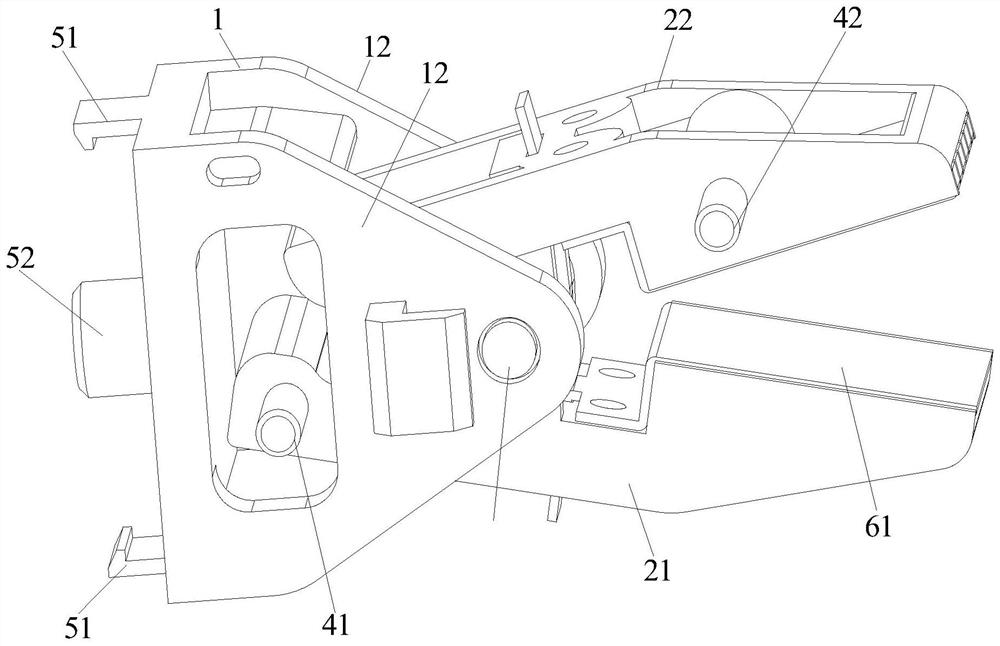
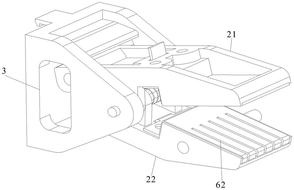
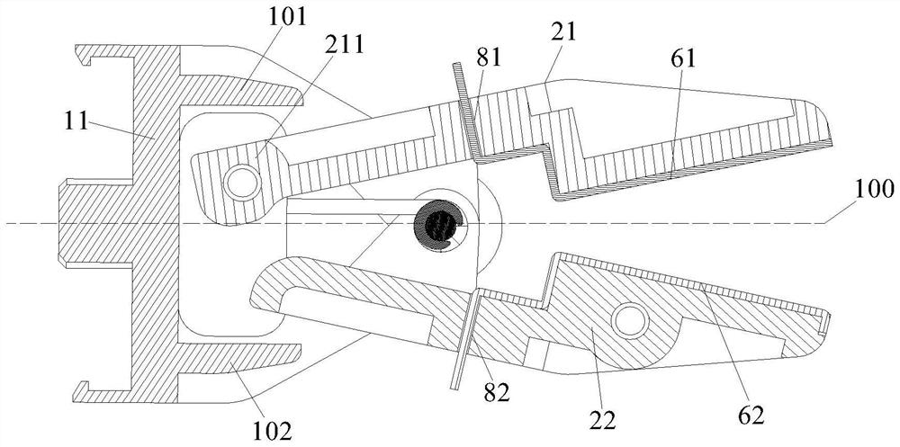
The invention discloses a lithium battery clamping mechanism with accurate clamping force. The lithium battery clamping mechanism comprises a base, a first clamping part, a second clamping part, a current metal sheet and a voltage metal sheet, wherein the first clamping part and the second clamping part are pivotally mounted on the base; the current metal sheet and the voltage metal sheet are respectively arranged on the first clamping part and the second clamping part; the voltage metal sheet is composed of a plurality of sheet bodies, the base is provided with a first pivoting part and a second pivoting part which are oppositely arranged, a rotating shaft is arranged between the first pivoting part and the second pivoting part, and the middle of the first clamping part and the middle of the second clamping part are installed on the rotating shaft in a pivoted mode. The rotating shaft is provided with an elastic piece which drives the front end of the first clamping part and the front end of the second clamping part to be attached to each other or away from each other. And a first clamp opening pin and a second clamp opening pin which are arranged in a staggered manner by taking the rotating shaft as a base point respectively and horizontally extend from the side walls of the first clamping part and the second clamping part. Through the cooperation of the first clamp opening pin, the second clamp opening pin, the limiting mechanism and the guide structure, the stress on the two sides of the tab can be uniform.

Description

technical field [0001] The invention relates to the field of lithium battery formation equipment, in particular to a lithium battery clamping mechanism with precise clamping force. Background technique [0002] Based on the current lithium battery formation equipment battery tab pressing device, especially the double-ended tab battery, the tab clamping method is mostly a one-torch eight-iron sheet pressing type. This method cannot implement a single-point control formation for the battery. The formation data of each battery cannot be recorded, the clamping force of each battery tab cannot be guaranteed to be consistent, and the battery data cannot be tracked in the later stage, and it adopts a two-wire system (only the detection of current input), which cannot accurately collect battery information. The quality of the finished product is not guaranteed. At the same time, because the clamping force cannot be kept consistent, it is easy to cause indentation on one side of the...

Claims


Application Information

Patent Timeline
Patent Type & Authority Applications(China)
IPC IPC(8): H01M10/44H01M10/058H01M10/052
CPCH01M10/44H01M10/058H01M10/052
Inventor 何志凌伍歌颂严勇
Owner 广东锦熹智能科技有限公司
Why Eureka
Try Eureka