Intelligent negative pressure collector based on negative pressure drainage system

A technology of negative pressure collection and drainage system, which is applied in the direction of waterway system, sewer pipe system, and sewage discharge, etc. It can solve the problems of inability to analyze the cause and location of the fault, consume a lot of time, and reduce the overall efficiency, etc., to achieve stable growth Open the components, facilitate positioning and maintenance, and ensure stable opening effects

Inactive Publication Date: 2021-09-17
江苏清川同创科技有限公司
View PDF7 Cites 0 Cited by
  • Summary
  • Abstract
  • Description
  • Claims
  • Application Information

AI Technical Summary

Problems solved by technology

Among them, the failure of the collector is mostly due to damage to system components and other reasons, which lead to the failure of the negative pressure intelligent collector, and the sewage cannot be collected in time, resulting in the phenomenon of cross flow at the bottom of the sewage; excessive work of the collector is manifested by continuous pressure relief of the system, and the pump Station pressure relief, continuous alarm, overall efficiency decline
At the present stage, during the suction process of the product, because the pipeline is always below the liquid level, it is impossible to enter the sewage and gas at the same time, which seriously damages the gas-liquid ratio inside the system.
At the same time, the current product can only predict the pressure relief of the system at the pumping station, but cannot analyze the specific cause and location of the failure, which leads to the need to spend a lot of time to find the failure point and repair it in the later maintenance

Method used


Image

  • Intelligent negative pressure collector based on negative pressure drainage system
  • Intelligent negative pressure collector based on negative pressure drainage system
  • Intelligent negative pressure collector based on negative pressure drainage system

Examples


Embodiment Construction

[0024] The preferred embodiments of the present invention will be described in detail below in conjunction with the accompanying drawings, so that the advantages and features of the present invention can be more easily understood by those skilled in the art, so as to define the protection scope of the present invention more clearly.

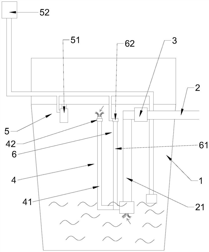
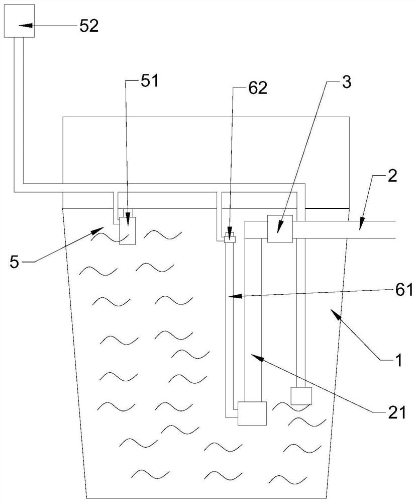
[0025] See attached Figure 1-5 As shown, an intelligent negative pressure collector based on a negative pressure drainage system in this embodiment includes a negative pressure intelligent collector 1, a negative pressure collecting pipe 2 is arranged in the negative pressure intelligent collector 1, and a negative pressure collecting pipe 2 The interface valve 3 is set on the top, and the interface valve 3 can control the on-off of the negative pressure collection pipe 2, and the air intake assembly 4 is arranged on the water absorption section 21 of the negative pressure collection pipe 2, and the air intake assembly 4 can adjust the air in the...


PUM


Abstract

The invention discloses an intelligent negative pressure collector based on a negative pressure drainage system. A negative pressure collecting pipe is arranged in the intelligent negative pressure collector, an air inlet assembly is arranged on a water suction section of the negative pressure collecting pipe, and the air inlet assembly can adjust the gas-liquid ratio in the water suction section; a stable opening assembly is arranged between an interface valve and the negative pressure collecting pipe, and the interface valve can be stably opened through the stable opening assembly; a fault alarm assembly is further arranged in the intelligent negative pressure collector and can detect the liquid level and give an alarm; and a flow monitoring assembly is further arranged in the water suction section and can detect the flow, recognize faults and give an alarm when faults occur. The air inlet assembly is arranged in the intelligent negative pressure collector, the flow speed can be increased, the suction process can be accelerated, the fault alarm assembly and a flow detection module are additionally arranged, system faults can be monitored in time, detected signals can be sent to a data information platform in real time, and fault points can be conveniently positioned and maintained.

Description

technical field [0001] The invention relates to the field of negative pressure drainage systems, in particular to an intelligent negative pressure collector based on the negative pressure drainage system. Background technique [0002] The negative pressure drainage system is a system that uniformly collects the sewage distributed in the negative pressure intelligent collector at the end of the tree-shaped negative pressure collection pipe network into the negative pressure power center at the end of the system through negative pressure. Therefore, as the number of negative pressure collectors increases, the number of failures also increases significantly, so the failure of negative pressure collectors greatly affects the stability of the entire negative pressure drainage system. [0003] However, the existing negative pressure intelligent collector includes a water collection terminal, a sewage suction pipe, an interface valve, a pilot valve and a liquid level switch. At pr...

Claims


Application Information

Patent Timeline
Patent Type & Authority Applications(China)
IPC IPC(8): E03F3/02E03F1/00G08B21/18G01D21/02
CPCE03F3/02E03F1/00E03F1/006G08B21/18G01D21/02E03F2201/20
Inventor 许庆成原嘉欣赵吉孟凡书
Owner 江苏清川同创科技有限公司
Why Eureka
Try Eureka