
A household cable safety monitoring device

A safety monitoring and cable technology, applied in the direction of measuring devices, measuring electricity, short-circuit testing, etc., can solve problems such as leakage, households are prone to electric shock, electric shock accidents, etc., and achieve the effects of improving work efficiency, narrowing the scope of monitoring, and improving accuracy

Active Publication Date: 2020-08-04
贵州首为电线电缆有限公司
View PDF4 Cites 0 Cited by
  • Summary
  • Abstract
  • Description
  • Claims
  • Application Information

AI Technical Summary

Problems solved by technology

[0003] The biggest problem with the current production process is that it is impossible to accurately control the thickness of the insulating protective layer during the production process. At present, it can only be roughly determined. Once the raw material of rubber foam contains impurities, resulting in mistakes in the heating and wrapping process, Then there will be loopholes in the insulation protection layer of the finished cable produced
Even if the finished cable is qualified and there are no leaks in the insulation protection layer, the insulation protection layer will be aged and worn after the cable is used for a long time, especially household cables are easy to be bitten off by mice or heavy objects such as furniture are crushed. Once this section of cable is used normally, it will cause the transmission performance to drop, or cause electric leakage, or even cause electric shock accidents.
Moreover, for household cables, residents generally ignore the safety monitoring of cables, that is, residents are prone to electric shock during use, which poses a safety hazard to the lives of residents.

Method used


Image

  • A household cable safety monitoring device

Examples


Embodiment Construction

[0019] Further detailed explanation through specific implementation mode below:

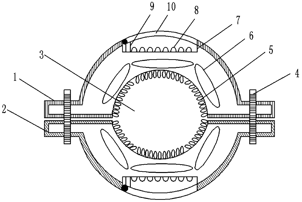
[0020] The reference signs in the drawings of the specification include: upper splint 1, lower splint 2, through groove 3, bolt 4, metal conductive contact 5, storage bag 6, cavity 7, colored lamp 8, normally open switch 9, second A magnet cover 10 .

[0021] like figure 1 The household cable safety monitoring device shown includes an upper splint 1 and a lower splint 2, the upper splint 1 is detachably connected to the top surface of the lower splint 2 through a connector, and the middle sections of the upper splint 1 and the lower splint 2 are aligned The outer arch forms a slot 3 through which the cable passes for detection. Among them, the connecting piece is a bolt 4, and the two ends of the upper splint 1 and the lower splint 2 are correspondingly provided with threaded holes matching the bolt 4, and the connection between the bolt 4 and the threaded hole is provided with a rubber anti-ru...


PUM


Abstract

The present invention relates to the technical field of cable monitoring, and discloses a domestic cable safety monitoring device. The device comprises an upper clamping plate and a lower clamping plate, middle sections of the upper clamping plate and the lower clamping plate are hunched up outwards to form a straight slot which allows a cable to pass through, the inner wall of the straight slot is provided with metal conductive contacts, and the metal conductive contacts communicate with an induction coil; a cavity and a material storage bag are clamped at the internal portions of the upper clamping plate and the lower clamping plate, the cavity is internally provided with a fancy lantern and a normally open switch, the side wall of the cavity is provided with an opening, the opening is hinged with a first magnet cover which can be opened when the induction coil is electrified to generate a magnetic field, and the normally open switch is pressed when the first magnet cover encloses the cavity; and the material storage bag is hinged with a second magnet cover which can be opened when the induction coil is electrified to generate a magnetic field, the material storage bag is internally provided powder which can be fell on a cable core when the second magnet cover is opened. The domestic cable safety monitoring device can monitor the condition of domestic cable leakage, can markportions of cable leakage and can facilitate location maintenance by workers.

Description

technical field [0001] The invention relates to the technical field of cable monitoring, in particular to a household cable safety monitoring device. Background technique [0002] A cable is made of one or more mutually insulated cores and an outer insulating layer, and is a wire that transmits power or information from one place to another. The cable has the characteristics of internal electrification and external insulation. The current insulating protective layer is basically made of rubber material or foam material, but whether it is rubber material or foam material, the production of cables is to wrap the heated and softened rubber material or foam material on the cable core. [0003] The biggest problem with the current production process is that it is impossible to accurately control the thickness of the insulating protective layer during the production process. At present, it can only be roughly determined. Once the raw material of rubber foam contains impurities, r...

Claims


Application Information

Patent Timeline
Patent Type & Authority Patents(China)
IPC IPC(8): G01R31/52G01R31/58
CPCG01R31/50G01R31/58
Inventor 韦首
Owner 贵州首为电线电缆有限公司
Learn More